Operation device and bending operation device of endoscope

a technology of operation device and endoscope, which is applied in the direction of mechanical control device, manual control with single controlling member, instruments, etc., can solve the problem that the bending of the operation shaft itself of the joystick to the neutral position is not influenced by non-uniform attachment, so as to prevent the occurrence of non-smooth operation

Active Publication Date: 2008-11-06
OLYMPUS CORP
View PDF11 Cites 23 Cited by
  • Summary
  • Abstract
  • Description
  • Claims
  • Application Information

AI Technical Summary

Benefits of technology

[0026]In the above structure, the oblique portion at the periphery of the through-hole of the movement member is put in contact with the spherical portion of the hollow body of the operation shaft in a direction at an acute angle, which is inserted in the through-hole of the movement member that is formed of the plate-shaped member. Thereby, at the time of operating the operation shaft, the operation force of the operation shaft is transmitted to the movement member while the hollow body is being moved in the axial direction of the operation shaft, and movement member is moved in the axi

Problems solved by technology

Thus, by attaching the rubber boot in accordance with the neutral position of the joystick, the restoration of the operatio

Method used


Image

  • Operation device and bending operation device of endoscope
  • Operation device and bending operation device of endoscope
  • Operation device and bending operation device of endoscope

Examples


first embodiment

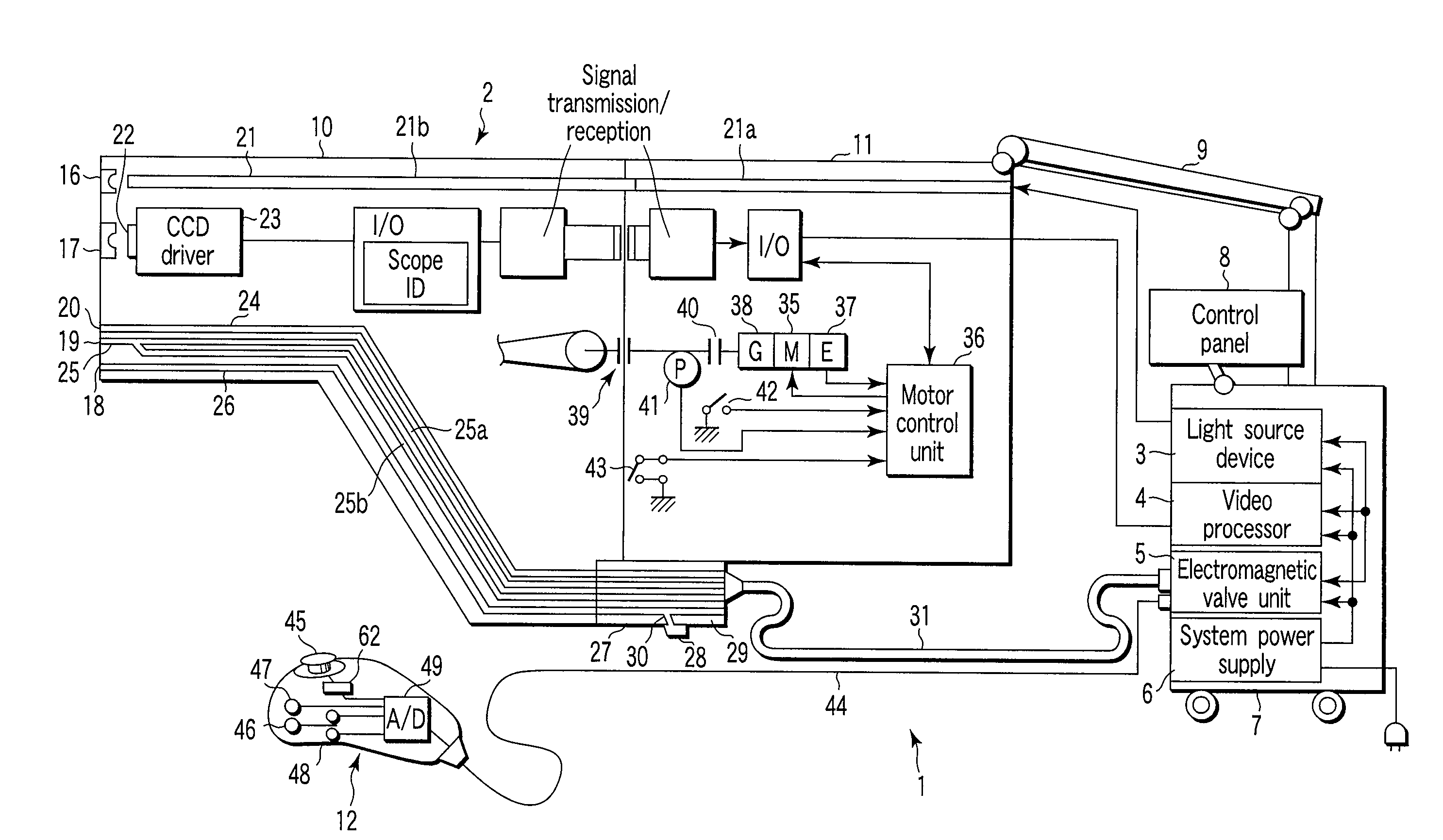
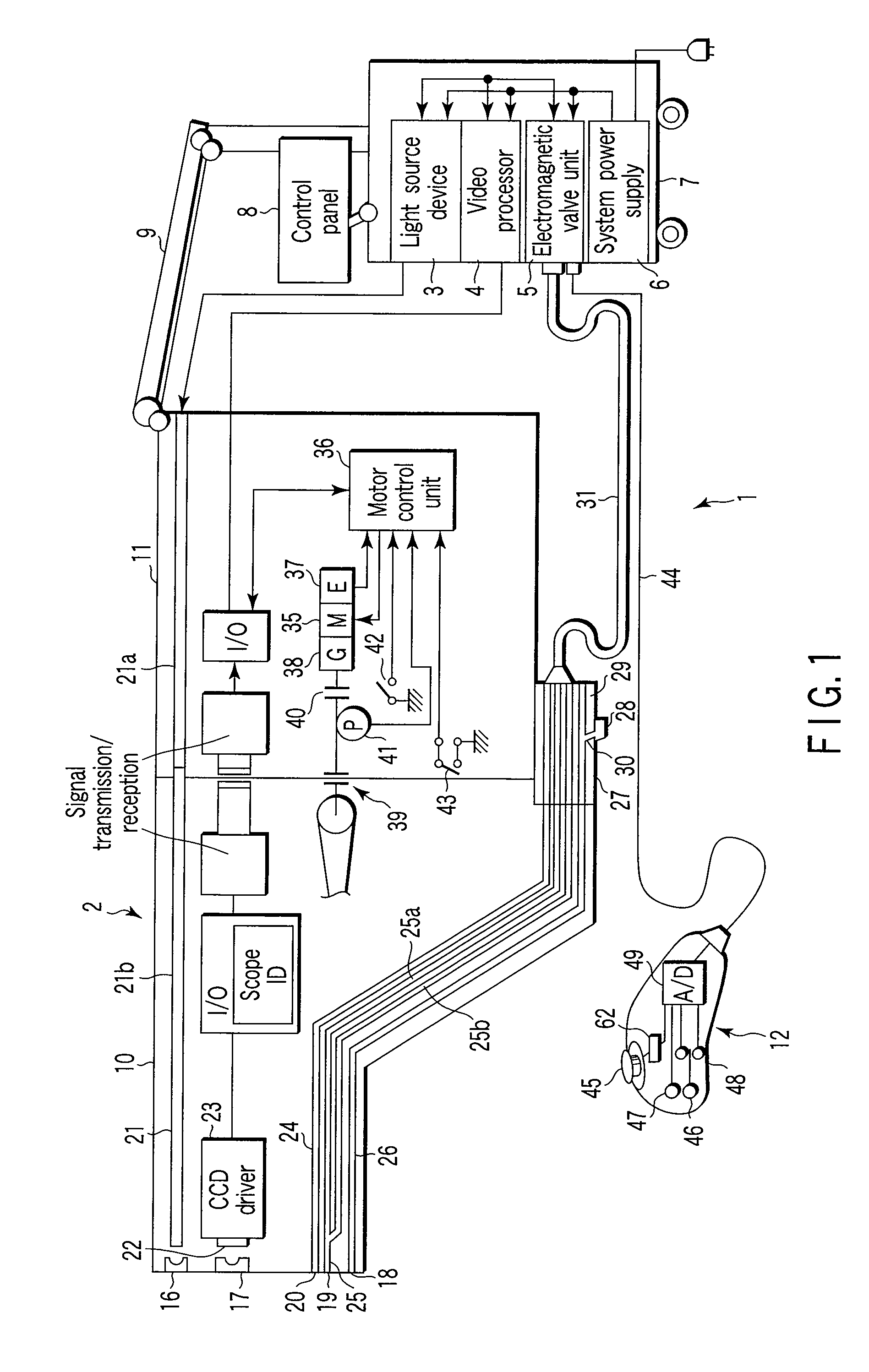
[0065]A first embodiment of the present invention will now be described with reference from FIG. 1 to FIG. 6. FIG. 1 is a schematic structural view of the entire system of a motor-driven bending endoscope apparatus 1 according to the present embodiment. The motor-driven bending endoscope apparatus 1 according to this embodiment mainly comprises a motor-driven bending endoscope 2, a light source device 3, a video processor 4, an electromagnetic valve unit 5, and a system power supply 6.

[0066]The motor-driven bending endoscope apparatus 1 is provided with a cart 7 which is configured to include, for example, casters, so as to make the motor-driven bending endoscope apparatus 1 freely movable on the floor. The cart 7 contains, in a stacked state, the light source device 3, video processor 4, electromagnetic valve unit 5 and system power supply 6.

[0067]The cart 7 further includes a display unit (not shown), a control panel 8 and an endoscope holding device 9. The display unit receives a...


PUM


Abstract

In the present invention, there are provided a movement member which includes an engaging section, which is engaged with an intermediate part of an operation shaft of a joystick device, and operates as one body with the operation shaft at a time of performing an inclining operation of the operation shaft, and a damper case in which the movement member is movably inserted, and which holds a viscous fluid which increases a sliding resistance of the movement member when the movement member is moved. Thereby, a desired operational sensation can be always obtained, and a stable bending operation can be performed.

Description

CROSS-REFERENCE TO RELATED APPLICATIONS[0001]This is a Continuation Application of PCT Application No. PCT / JP2006 / 322078, filed Nov. 6, 2006, which was published under PCT Article 21(2) in Japanese.[0002]This application is based upon and claims the benefit of priority from prior Japanese Patent Application No. 2005-327616, filed Nov. 11, 2005, the entire contents of which are incorporated herein by reference.BACKGROUND OF THE INVENTION[0003]1. Field of the Invention[0004]The present invention relates to an operation device which bend-operates, by motor driving, a bending section that is provided at a distal end side of an insertion section of an endoscope, and to a bending operation device of the endoscope.[0005]2. Description of the Related Art[0006]In general, a flexible endoscope, in which an insertion section that is to be inserted into the body has flexibility, has widely been used. The insertion section of the flexible endoscope includes an elongated flexible tube section, a ...

Claims


Application Information

Patent Timeline
IPC IPC(8): A61B1/005
CPCA61B1/0052G05G5/04G05G25/04Y10T74/20201G05G2009/04766A61B1/0016G05G2009/04707A61B1/00042
Inventor KOITABASHI, MASANOBU
Owner OLYMPUS CORP
Why Eureka
Try Eureka