Use of line characterization to configure physical layered devices

a physical layer device and characterization technology, applied in the field of networkworking, can solve the problems of long filter, underutilized, burdening the system, etc., and achieve the effect of optimizing filter performance, reducing a dynamic range in the filter, and reducing bits of precision in the filter

Active Publication Date: 2008-11-06
KEYEYE COMM
View PDF25 Cites 4 Cited by
  • Summary
  • Abstract
  • Description
  • Claims
  • Application Information

AI Technical Summary

Benefits of technology

[0008]The current invention is a method of optimizing filter performance through monitoring channel characteristics. In one embodiment of the invention, the method includes providing a signal into a channel and providing a receiver to receive the signal. The receiver includes a finite impulse response (FIR) filter disposed to remove a transmitted interfering signal from the signal in the channel and to recover a far end desired signal. The FIR filter includes a plurality of storage elements configured as a shift register to move the signal, multipliers to multiply the signal by a filter coefficient and provide a multiplied result, an intermittent summer to combine the multiplied results into a replica of an interfering signal, a final summer to remove the replica from the receiver signal, providing direct monitoring of the signal. The direct monitoring includes time monitoring or frequency monitoring and providing indirect monitoring of the signal. The indirect monitoring includes signal to noise ratio (SNR) monitoring, error magnitude monitoring or bit error rate (BER) monitoring. The current embodiment further includes optimizing the filter according to the monitoring. The optimization is selected from a group consisting of reducing a dynamic range in the filter, reducing bits of precision in the filter, reducing linearity of the filter, disabling the filter, and reallocating filter.

Problems solved by technology

However, often times the filter must include numerous taps to accommodate multiple operational circumstances, resulting in a lengthy filter that is over-designed, underutilized and burdensome to the system.

Method used


Image

  • Use of line characterization to configure physical layered devices
  • Use of line characterization to configure physical layered devices
  • Use of line characterization to configure physical layered devices

Examples


Embodiment Construction

[0019]Although the following detailed description contains many specifics for the purposes of illustration, anyone of ordinary skill in the art will readily appreciate that many variations and alterations to the following exemplary details are within the scope of the invention. Accordingly, the following preferred embodiment of the invention is set forth without any loss of generality to, and without imposing limitations upon, the claimed invention.

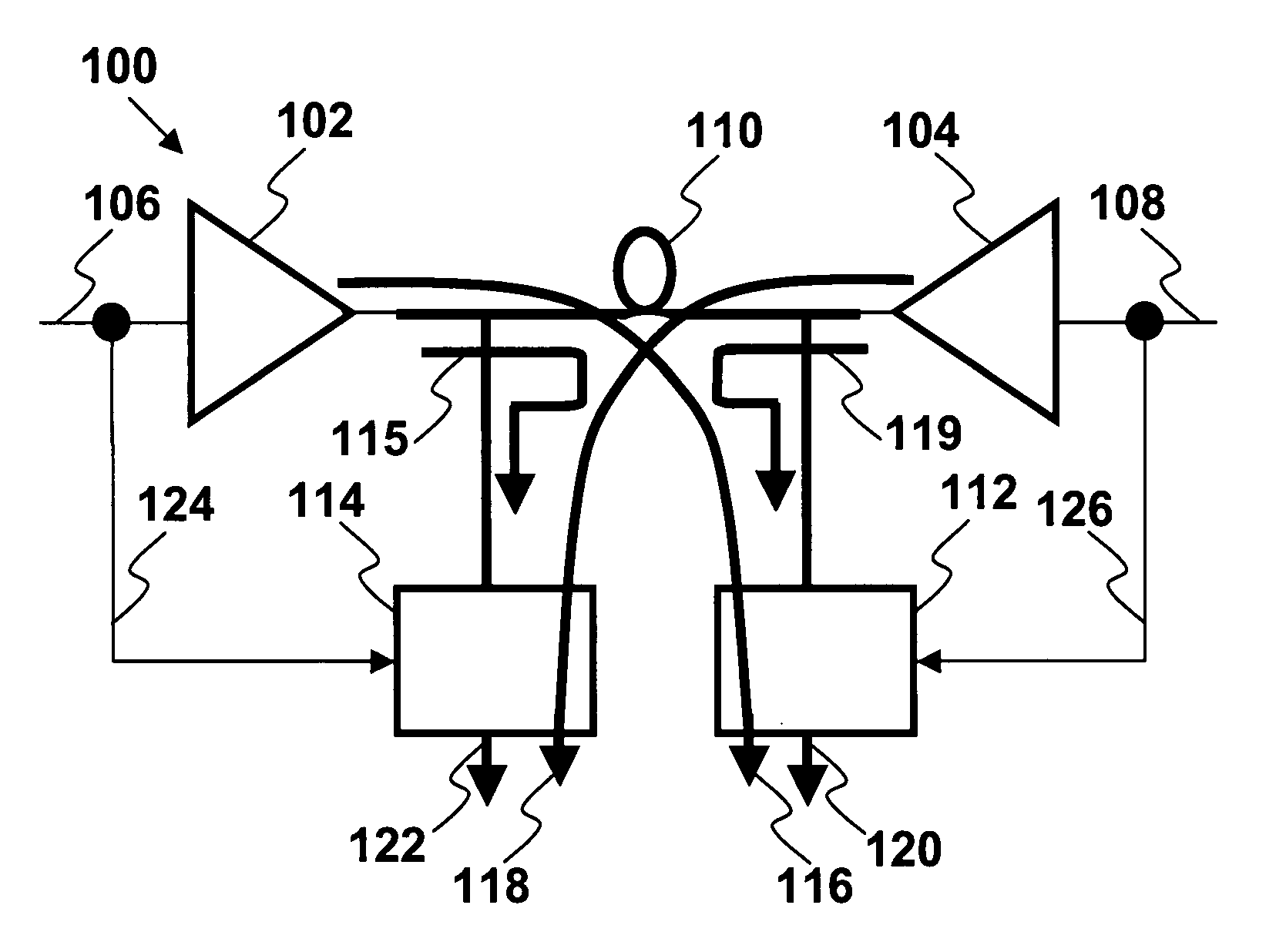
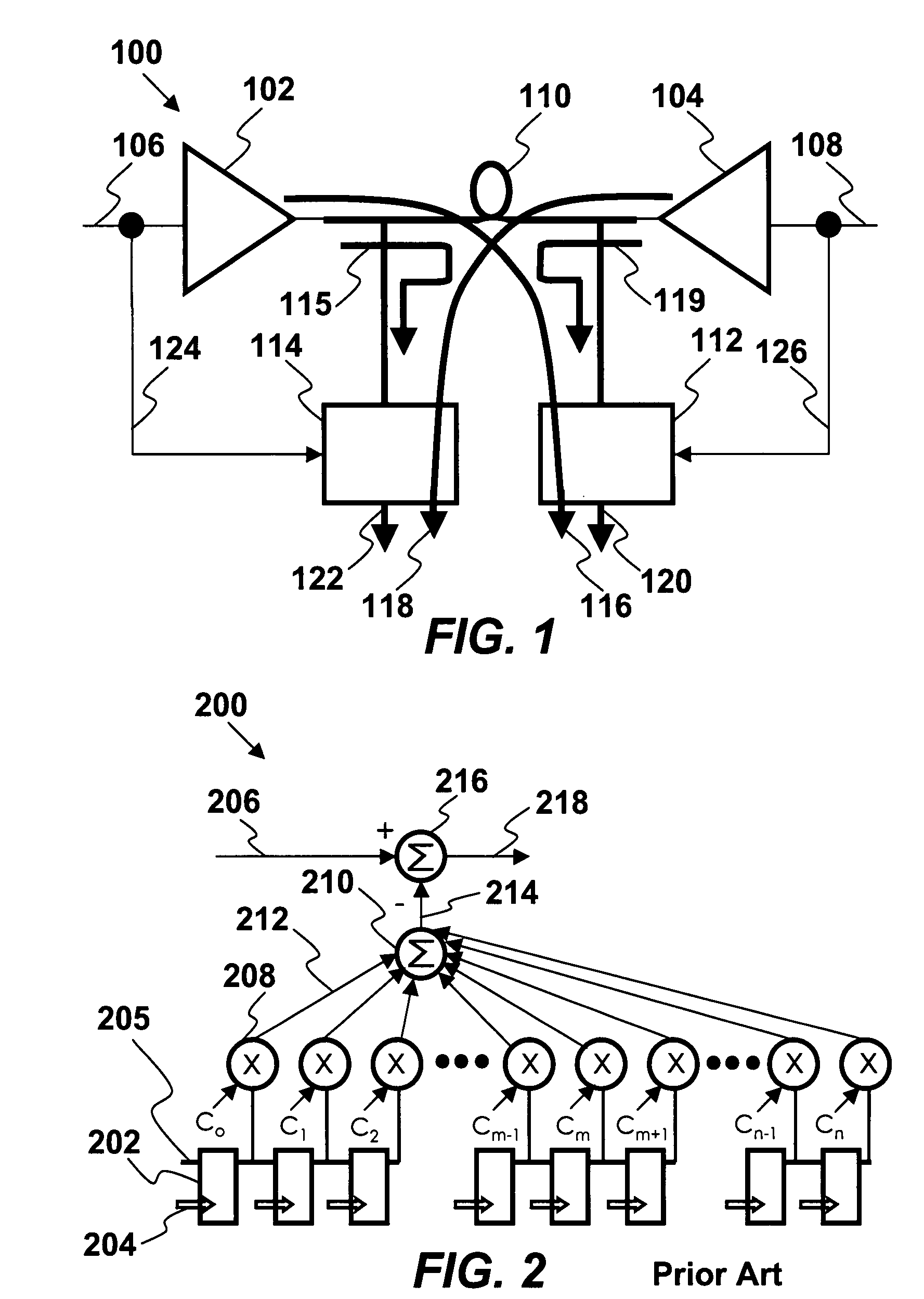
[0020]By monitoring the characteristics of the channel, filters may be optimized to improve performance. The monitoring may be direct, in the form of time of frequency domain parameters, or indirect, by measuring the signal-to-noise ratio (SNR) of bit error rate (BER). Optimization of the filter may include reducing their required dynamic range, bits of precision, linearity or disabling them altogether. Further, limited filter resources may be reallocated to where they would be most useful, such as delaying finite impulse response (FIR) f...


PUM


Abstract

A method of optimizing filter performance through monitoring channel characteristics is provided. A signal enters a channel and a receiver receives the signal. The receiver includes a FIR filter to remove near-end transmitted interference and recover a far-end desired signal. The filter has storage elements configured as a shift registers to move the signal, multipliers to multiply the signal by a filter coefficient, an intermittent summer to combine the multiplied results into a replica of an interfering signal, a final summer to remove the replica from the receiver signal to provide direct and indirect monitoring of the signal, where direct monitoring includes time or frequency monitoring, and indirect monitoring includes monitoring signal to noise ratio, error magnitude or bit error rate. The filter is optimized according to monitoring and includes reducing a dynamic range, reducing bits of precision, reducing linearity, the filter, and reallocating the filter.

Description

FIELD OF THE INVENTION[0001]The invention relates generally to networking. More particularly, the invention relates to a method of optimizing filter performance through monitoring channel characteristics in a network.BACKGROUND[0002]Recent telecommunications technology has improved communication efficacy. Advanced methods of communications require creative solutions to problems encountered in implementing such advancements. Finite impulse response (FIR) filters are commonly used in high-speed data communications electronics for cancellation of interfering signals, such as echo, near-end crosstalk (NEXT) and far-end crosstalk (FEXT). Below is described a system for canceling echo.[0003]A FIR filter is typically implemented by using a series of delays, multipliers, and adders to create the filter's output. The process of selecting the filter's length and coefficients is in the filter design, where the design effort should result in a frequency response which meets the desired specific...

Claims


Application Information

Patent Timeline
Patent Type & Authority Applications(United States)
IPC IPC(8): G06F17/10H04L47/52H04L47/722
CPCG06F1/10H04J3/0697H04B3/32H03L7/00H04L25/0278H04L43/16H04L47/25H04L47/6215H04L47/521H04L47/6245H04L47/722
Inventor CALLICOTTE, MARK JOSEPHTAKATORI, HIROSHI
Owner KEYEYE COMM
Why Eureka
Try Eureka