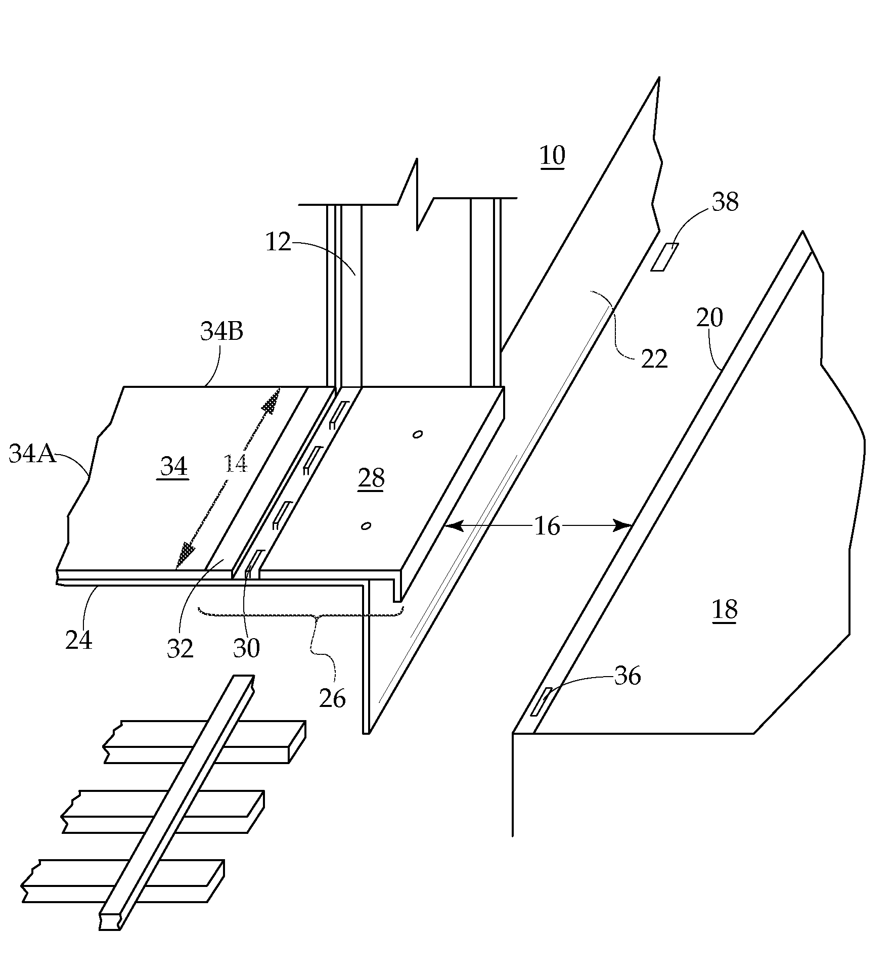
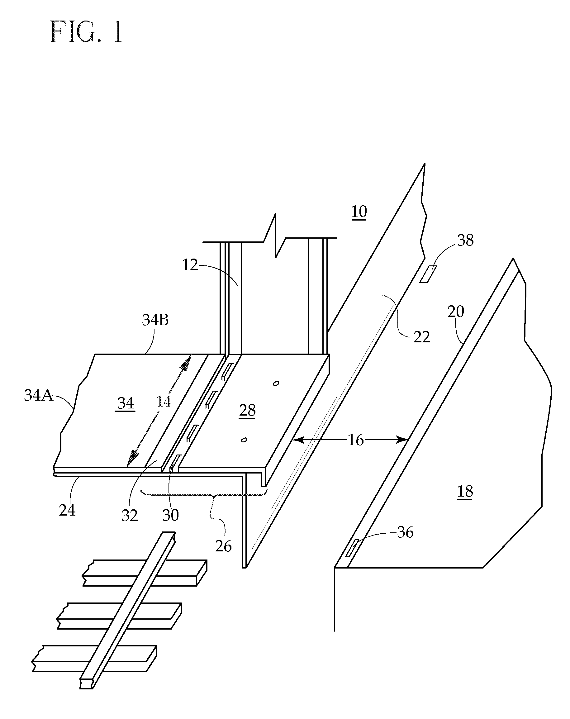
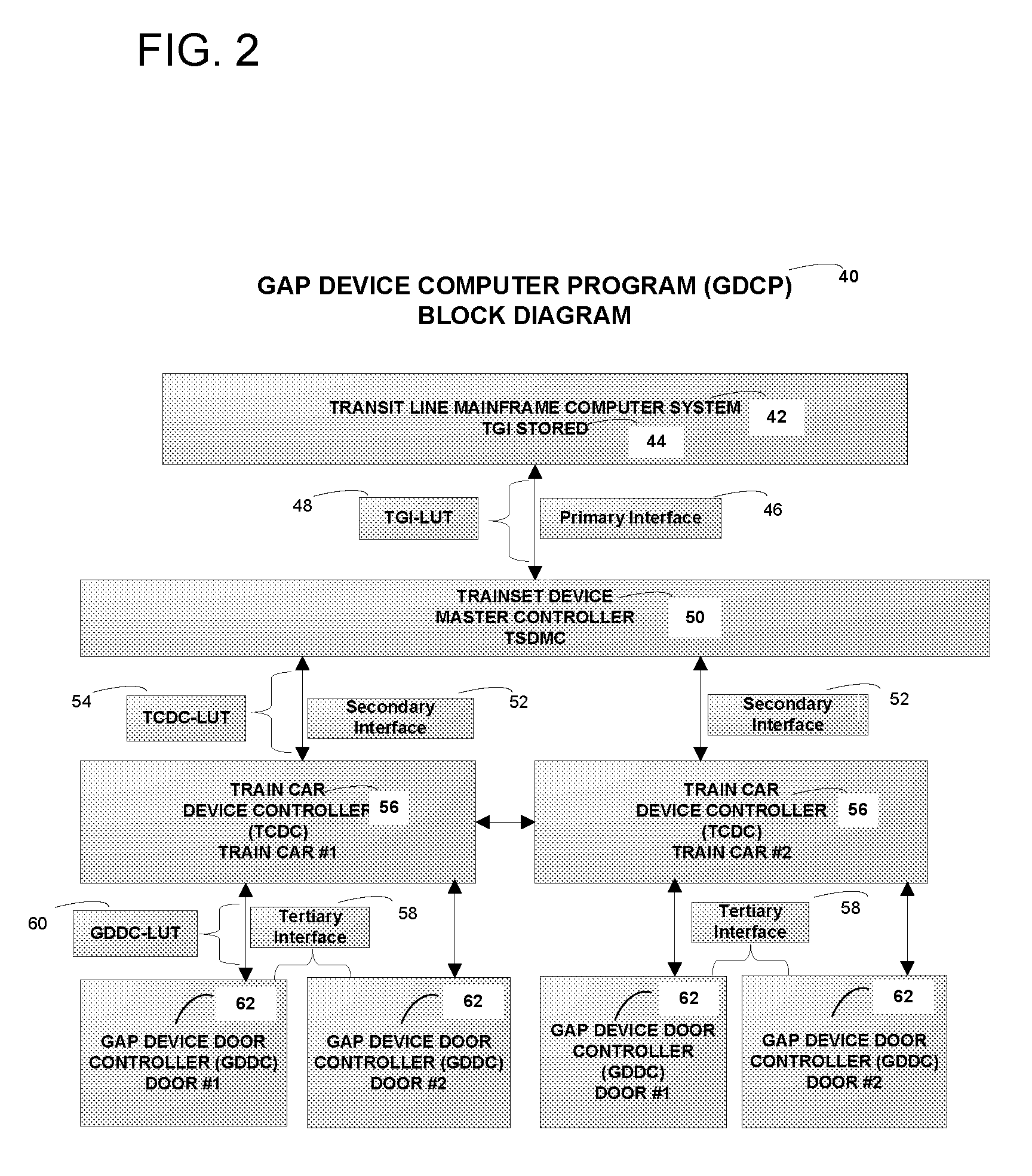
Train-to-platform gap mitigator

a technology of platform and train, which is applied in the direction of railway stations, locomotives, railway lines, etc., can solve the problems of complex problem and its attendant solution, insufficient functional analysis and formulation, and inability to achieve the goal of train lines, so as to minimize every horizontal gap and facilitate the goal of the train line

Active Publication Date: 2008-11-13
CHISENA MICHAEL P
View PDF31 Cites 24 Cited by
  • Summary
  • Abstract
  • Description
  • Claims
  • Application Information

AI Technical Summary

Benefits of technology

[0050]The device of the present invention facilitates the goal of the train line to minimize every horizontal gap, regardless of size, on every train route within its entire transit line system through utilization of the flexibility offered by the various embodiments of the device while maintaining adherence to the system's side clearance standards and requirements.
[0051]The device of the present invention permits every rail carrier to operationally provide from the horizontal perspective full train length level entry boarding as now, or as may be, mandated by the ADA and its accompanying DOT regulations at each train car doorway of every train forming the trainset when stopping at every station on its train line regardless of track type thereby providing full integrated service to all cars to all persons with disabilities. Utilization of the invention's device will permit each rail carrier including, but not limited to, light rail, commuter rail and intercity rail systems to provide full train length level entry boarding, as stated above, without the necessity of attempting to demonstrate to any applicable governmental oversight authority that it is not operationally or structurally feasible to meet the horizontal gap requirement thereby requiring an authorized alternative means to provide accessibility.

Problems solved by technology

Gap widths in train stations along the plurality of routes of a transit line system are not uniform in size.
It is functionally inadequate to analyze the issue and formulate solutions solely from the perspective of considering every train station within a transit line system as having a uniform gap width along its entire platform.
The problem and its attendant solution is made further complex due to the fact that any particular train car may be routinely transferred from one route to another route within the transit line system and which action will present differing gap size issues for each train car doorway of that train on its new route.
There is no device which functionally addresses gap mitigation solutions for the varying sized gaps existing at each train car doorway with its corresponding train station platform edge of every train of a trainset at every station along a train's route.
The devices known to exist claiming to respond to the need for gap mitigation are universally burdened by the common deficiency of having a singular non-flexible approach and thereby being unable to address the goal of mitigating every sized gap at every train car doorway with its corresponding station platform.
Disadvantageously, device utilization presumes that for the entire length of each train station platform, the platform must be lower than each train car doorway throughout the entire transit line system or the device cannot be used.
A further distinctive disadvantage is the preset operating position of the device limiting its extension to one predetermined length.
The device can be recalibrated to a different length but, most importantly, this cannot take place during the train's on-going route and must be accomplished during non-operating maintenance conditions.
There is no disclosed capability for the device to adjust its length of extension into the horizontal plane between the train and the station platform while the train is on its route.
Thus, the bridge plate type device will unnecessarily overlay the station platform at a plurality of different lengths varying train car doorway to doorway thereby creating an unwarranted and jigsaw-like series of tripping hazards along the entire platform adjacent to the train.
If the plate does not function according to design, an obvious hazard has been created due to the very location of the device against the exterior of the train car doorway thereby preventing door opening and closing procedures with consequent train delays.
A common disability of all bridge plate type devices, regardless of its stowed position, is created by the very nature of the apparatus having necessarily to rest upon the train station platform.
This problem is exacerbated during the commuter morning and evening rush hours.
More importantly, such devices do not address the need, without use of an apparatus which lays upon the train station platform with the attendant problems associated therewith, to mitigate different sized gaps at each doorway of each train on a trainset in every station on a train line's route.
As aforementioned, a tripping hazard is caused due to the introduction of an apparatus on a crowded platform.
Further, timing concerns have not been anticipated, or if so, are not taken into consideration in the implementation of the device pertaining to transit line scheduling.
All related art bridge plate devices suffer from the common deficiency of not being able to specifically address different sized gaps that a train at each train car doorway will encounter while that train is on its route and are relegated to use a one size fits all simplistic approach of having to reach and overlay the station platform.
Thus, for the entire length of the platform at each train station on all routes within a transit line system, the platform must be lower than each train car doorway of each train in the system's fleet, or the bridge plate type device cannot be used.
Therefore, such devices do not have practical use and cannot provide any measurable and meaningful gap solution.
An obvious disadvantage of this type device is the probability of unwanted collision between the device and various objects, including the station platform, it can potentially come into contact with during the train's route.
Thus, the selected fixed length of the extension would have to be severely limited by normal and expected operating conditions of any train.
It is apparent that the issue of passenger safety, which has come to the national forefront of discussion and concern, has been caused by the focus of attention presently being raised due to the increasing number of gap related incidents causing serious injuries to commuters.

Method used


Image

  • Train-to-platform gap mitigator
  • Train-to-platform gap mitigator
  • Train-to-platform gap mitigator

Examples


embodiment 216

[0293]FIGS. 22-23 disclose another preferred embodiment 216, that is, a variation of the aforesaid seventh plate structure now comprising a second slidable member 218 with its second slidable device 222, positioned below the plate component 184 of the present invention's device and to work in conjunction with said plate component 184, and to be incorporated within the frame 194 hereinabove described.

[0294]A second slidable member 218 is disclosed comprised of the following components: a structure having generally a U-shape 220; a plurality of said second slidable devices 222; a connecting shaft 226 appropriately fitted through a slotted opening 224 of each said second slidable device 222, and a structure having generally an inverted U-shape 228.

[0295]Preferably, there shall be two structures having generally said U-shape 220 to be incorporated within the second slidable member 218.

[0296]Each of the dual U-shaped components 220 forming a part of the second slidable member 218 is loca...

embodiment 238

[0311]FIGS. 24-27 disclose another preferred embodiment 238, that is, a further variation of the aforesaid seventh plate structure now comprising a third slidable member 240 with its third slidable device 244, positioned below the plate component 184 of the present invention's device and to work in conjunction with said plate component 184, and a separate structure 254 positioned above said plate 184, and all to be incorporated within the frame 194 hereinabove described.

[0312]A third slidable member 240 is disclosed comprised of the following components: a structure having generally a U-shape 242; a plurality of said third slidable devices 244; a connecting shaft 248 appropriately fitted through a slotted opening 246 of each said third slidable device 244, and a structure having generally an inverted U-shape 250.

[0313]Preferably, there shall be two structures having generally said U-shape 242 to be incorporated within the third slidable member 240.

[0314]Each of the dual U-shaped com...


PUM


Abstract

An improved gap filler in the form of a single plate or a plurality of plates attached to the train car exterior or emanating from below train car vestibule floor which permits transit line system operator to utilize one device to obtain any desired gap minimization at every train car door in a trainset relative to its corresponding platform edge at all stations on its transit line regardless of platform and / or track configuration while simultaneously adhering to its gap clearance standards pertaining to safe passage of any train within its fleet through any station.

Description

CROSS-REFERENCE TO RELATED APPLICATIONS[0001]This application claims the benefit of U.S. Provisional Application No. 60 / 928,922 filed May 11, 2007, the contents all of which are incorporated herein by reference.FIELD OF THE INVENTION[0002]The present invention generally relates to a new and improved method to minimize the gap between a train car doorway and train station platform.BACKGROUND OF THE INVENTION[0003]1. Introduction[0004]The gap is the horizontal space between the edge of the platform and the edge of the rail car door and the vertical difference from the top of the platform and the top of the rail car door. A horizontal gap of some size between a train and the train station platform is necessary to allow the safe passage of trains through stations. If the horizontal gap is too narrow, the dangerous potential exists that the train could strike the platform thereby causing train derailment, injury to commuters and damage to both the train and the platform. The complexities...

Claims


Application Information

Patent Timeline
Patent Type & Authority Applications(United States)
IPC IPC(8): B61K13/04
CPCB61D23/025B61K13/04
Inventor CHISENA, MICHAEL P.
Owner CHISENA MICHAEL P
Why Eureka
Try Eureka