Method and apparatus for making uniform and ultrasmall nanoparticles

a nanoparticle and ultra-small technology, applied in lighting and heating apparatus, physical/chemical process catalysts, prosthesis, etc., can solve the problems of turbulence within the quench region, disturbance of the flow of reactive mixtures, etc., and achieve uniform nanoparticles and rapid quenching of reactive mixtures

Active Publication Date: 2008-11-13
SDC MATERIALS +1
View PDF102 Cites 101 Cited by
  • Summary
  • Abstract
  • Description
  • Claims
  • Application Information

AI Technical Summary

Problems solved by technology

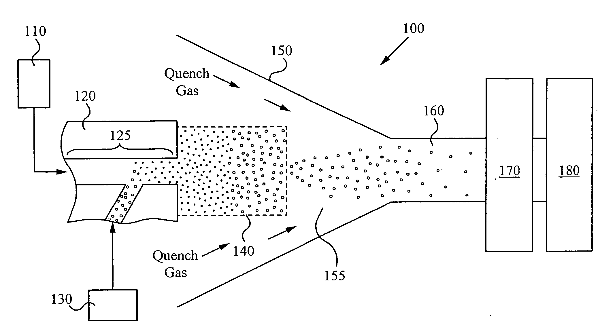
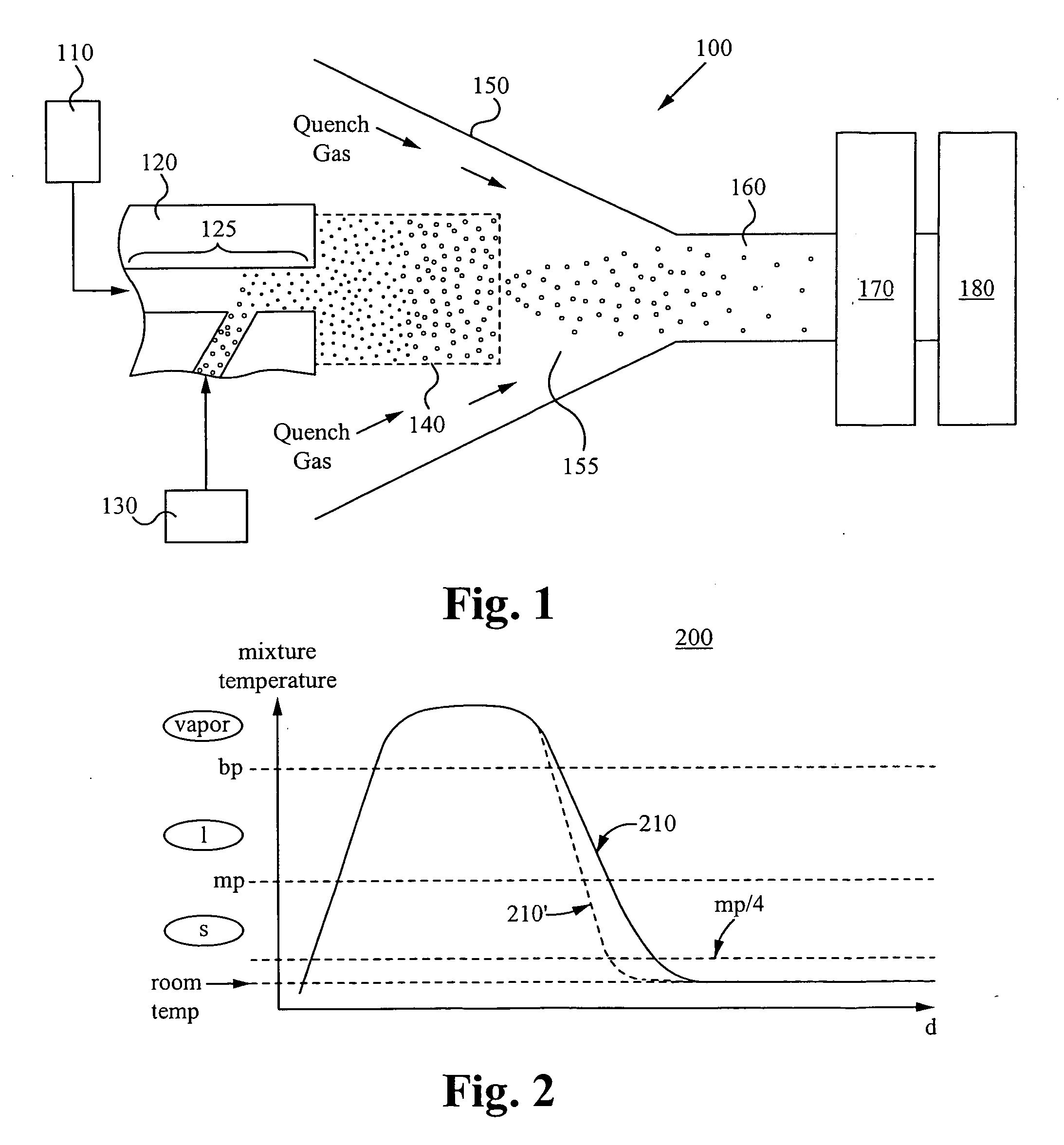
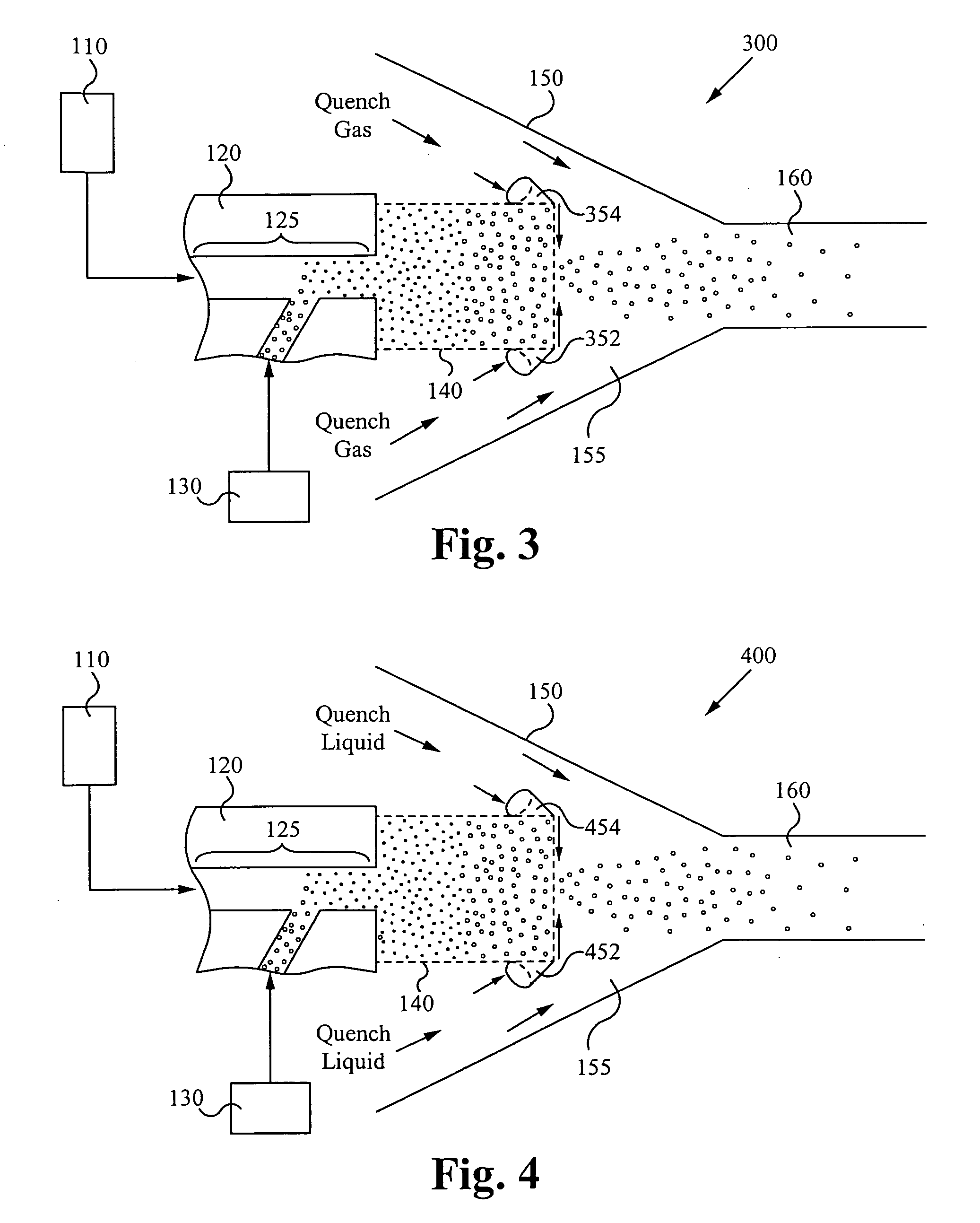
The conditioning fluid flows directly into the reactive mixture stream as the reactive mixture stream flows through the ejection port of the reaction chamber, thereby disturbing the flow of the reactive mixture stream and creating turbulence within the quench region.

Method used


Image

  • Method and apparatus for making uniform and ultrasmall nanoparticles
  • Method and apparatus for making uniform and ultrasmall nanoparticles
  • Method and apparatus for making uniform and ultrasmall nanoparticles

Examples


Embodiment Construction

[0023]The description below concerns several embodiments of the invention. The discussion references the illustrated preferred embodiment. However, the scope of the present invention is not limited to either the illustrated embodiment, nor is it limited to those discussed. To the contrary, the scope should be interpreted as broadly as possible based on the language of the Claims section of this document.

[0024]In the following description, numerous details and alternatives are set forth for purpose of explanation. However, one of ordinary skill in the art will realize that the invention can be practiced without the use of these specific details. In other instances, well-known structures and devices are shown in block diagram form in order not to obscure the description of the invention with unnecessary detail.

[0025]This disclosure refers to both particles and powders. These two terms are equivalent, except for the caveat that a singular “powder” refers to a collection of particles. T...


PUM

PropertyMeasurementUnit
grain sizeaaaaaaaaaa

Abstract

A system comprising: a plasma production chamber configured to produce a plasma; a reaction chamber vaporize a precursor material with the plasma to form a reactive mixture; a quench chamber having a frusto-conical surface and a quench region formed within the quench chamber between an ejection port of the reaction chamber and a cooled mixture outlet, wherein the quench region configured to receive the reactive mixture from the ejection port, to cool the reactive mixture to form a cooled mixture, and to supply the cooled mixture to the cooled mixture outlet; and a conditioning fluid injection ring disposed at the ejection port and configured to flow a conditioning fluid directly into the reactive mixture as the reactive mixture flows through the ejection port, thereby disturbing the flow of the reactive mixture, creating turbulence within the quench region and cooling the reactive mixture to form a cooled mixture comprising condensed nanoparticles.

Description

CROSS-REFERENCE TO RELATED APPLICATIONS[0001]The present application claims priority to co-pending U.S. patent application Ser. No. 11 / 110,341, filed on Apr. 19, 2005, entitled, “HIGH THROUGHPUT DISCOVERY OF MATERIALS THROUGH VAPOR PHASE SYNTHESIS” and to co-pending U.S. Provisional Application Ser. No. 60 / 928,946, filed May 11, 2007, entitled “MATERIAL PRODUCTION SYSTEM AND METHOD,” both of which are hereby incorporated by reference as if set forth herein.FIELD OF THE INVENTION[0002]The present invention relates to methods of and apparatus for quenching a reactive medium containing gas or vapor phase in order to produce uniform and ultrasmall nanoparticles.BACKGROUND OF THE INVENTION[0003]Gas or vapor phase particle production is an important technique for producing engineered nanoparticles. In a particle-producing reactor, basic product species are formed within extremely short time spans following ejection of a hot, reactive medium from an energy delivery zone. Following ejection...

Claims


Application Information

Patent Timeline
Patent Type & Authority Applications(United States)
IPC IPC(8): B01J19/08
CPCB22F9/12Y10T156/15F28D7/024F28D7/08F28D15/00F28F27/00B22F2999/00B01J19/0013Y10S623/923B01J25/00B01J25/02Y10S623/92B22F2202/13Y10T137/0391Y10T137/2076A61L2/18B22F2203/13B01J19/088B01J37/0018B01J37/349B01J37/06B01J2219/0805B01J2219/0894B01J2/16B01J35/04B01J37/0027B01J2219/0879F28C3/16
Inventor BIBERGER, MAXIMILIAN A.LAYMAN, FREDERICK P.
Owner SDC MATERIALS
Why Eureka
Try Eureka