
Gas Permeable Molds

a technology molds, which is applied in the field of gas permeable molds, can solve the problems of restricting the placement of vents, limiting the orientation of vents with respect to the molding surface, and expensive and time-consuming conventional vent-making processes

Inactive Publication Date: 2008-11-13
THE EX ONE
View PDF13 Cites 35 Cited by
  • Summary
  • Abstract
  • Description
  • Claims
  • Application Information

AI Technical Summary

Benefits of technology

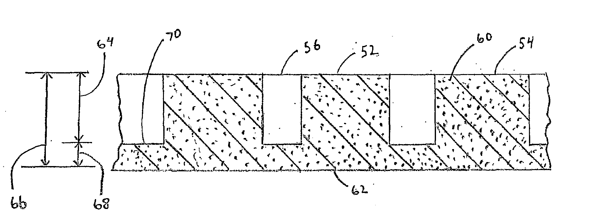
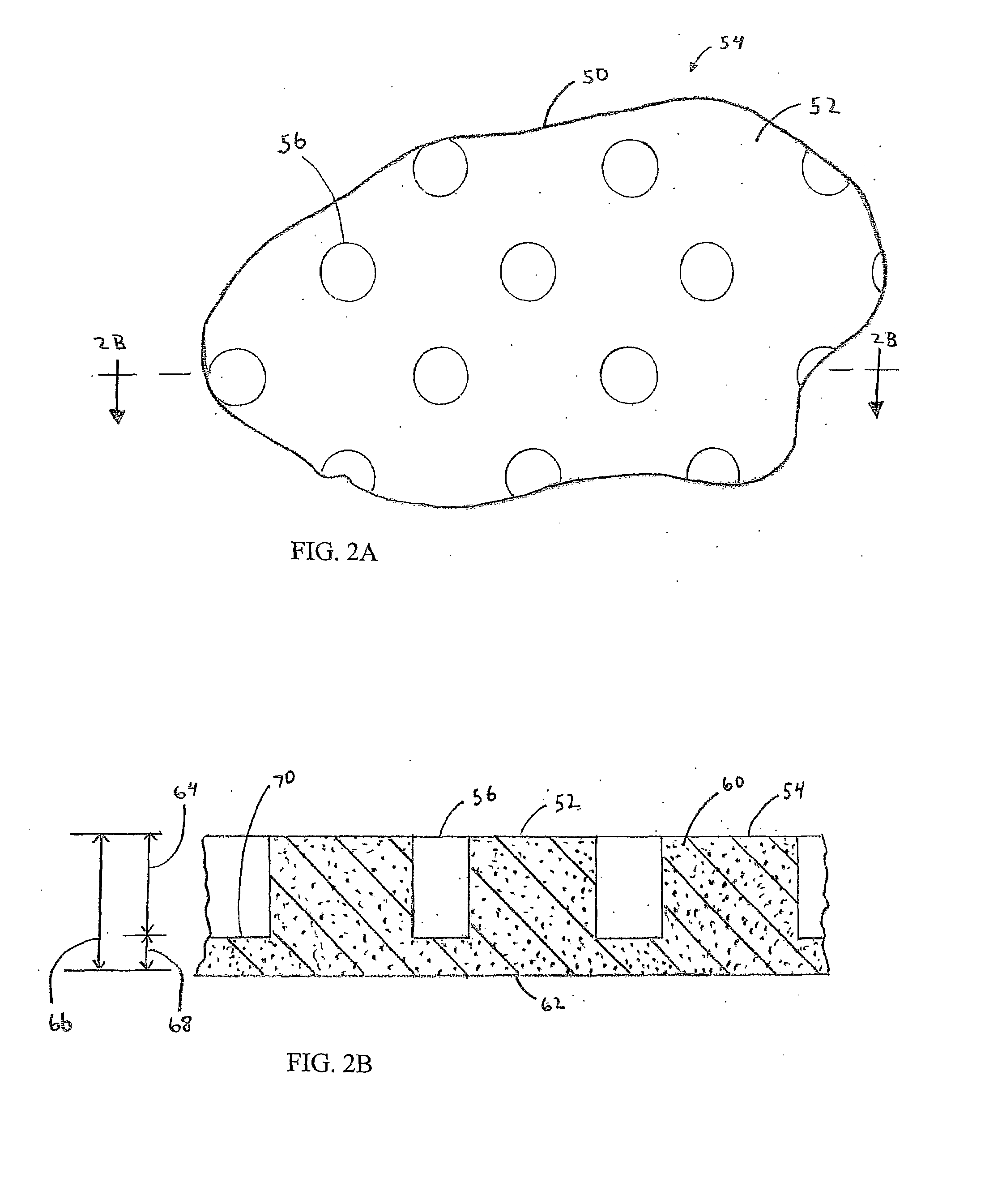
[0009]The use of blind vents provides several advantages. One, is that the molding surface is uninterrupted, thus avoiding the problem of nubs and vent patterns being formed on the surface of the molded article from where open vents intersect the molding surface of the mold or mold segment. Another is that it allows the coarseness of the open porosity to be reduced and so provides a smoother molding surface without sacrificing gas permeability. Third, it permits the wall thickness to be increased without compromising the mold's or mold segment's gas permeability thereby providing for a stronger and more robust mold or mold segment than is possible in prior art open porosity gas permeable molds and mold segments.
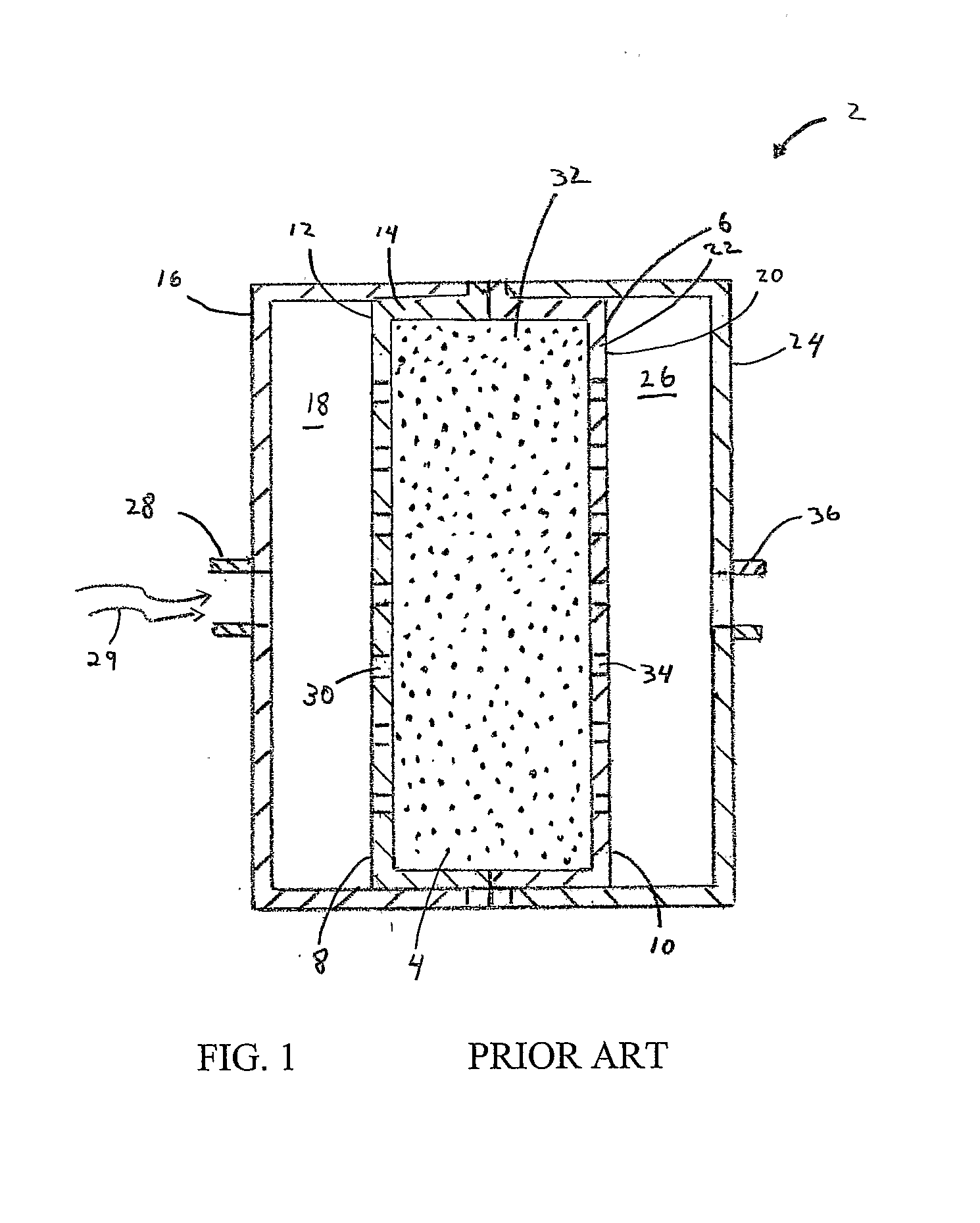
[0011]The present invention also includes embodiments in which a gas permeable EPS mold segment is part of a unitary structure with a steam chest. A steam chest is a plenum that surrounds a gas permeable EPS mold segment. A steam chest contains one or more ports for selectively conducting gas into or out of the steam chest cavity and the steam chest walls themselves are gas impermeable. The gas permeable EPS mold segment, however, has open porosity. The gas permeability of the gas permeable EPS mold segment may, but need not be, augmented by one or more vents, which may be open or blind vents or a combination of the two. The phrase “open vent” as used herein and in the appended claims refers to a vent that extends uninterrupted through a mold wall from the mold's outer surface to its molding surface. The present invention also includes methods for making such unitary structures in which the unitary structure is built by solid free-form fabrication. In such methods, the steam chest is made gas impermeable by infiltrating it with a solidifiable liquid. The unitary structure embodiments of the present invention have the advantage of utilizing the steam chest to strengthen the gas permeable mold against both the outwardly and the inwardly directed forces that it encounters during the molding operation. In contrast, when the steam chest is not integral with the gas permeable mold segment, it can only brace the gas permeable mold segment against outwardly directed forces.

Problems solved by technology

Conventional vent-making processes are costly and time consuming.
Moreover, they restrict the placement of vents to areas that are accessible to the tool that will be used for making the vent.
Another drawback is that the vent orientation with respect to the molding surface is restricted by the perforation technique employed and the accessibility of the portion of the surface at which an individual vent is to be placed.
Where the surface shape curves or is complex or access is limited, the vent is likely to have a less-than-optimal orientation.
A drawback to these prior art open-porosity molds is that their gas permeability is primarily dependent on the thickness of the mold wall and of the coarseness and amount of the porosity.
Because the porosity weakens the mold, the wall thickness must be increased over what it could be if a solid material were used, but this increased wall thickness reduces the gas permeability.
Further, the achievement of an operable balance may be at the cost of molding surface smoothness due to the coarseness of the porosity on the molding surface.

Method used


Image

  • Gas Permeable Molds
  • Gas Permeable Molds
  • Gas Permeable Molds

Examples


Embodiment Construction

[0020]In this section, some preferred embodiments of the present invention are described in detail sufficient for one skilled in the art to practice the present invention. It is to be understood, however, that the fact that a limited number of preferred embodiments are described herein does not in any way limit the scope of the present invention as set forth in the appended claims.

[0021]The present invention includes among its embodiments gas permeable molds for all applications in which gas permeable molds are used, e.g., for EPS bead molding, for injection molding, for vacuum forming, etc. Likewise, the present invention includes among its embodiments methods for making all such gas permeable molds. However, for clarity of illustration and conciseness, only preferred embodiments which relate to gas permeable molds for EPS bead molding are described. Similarly, while the methods of the present invention which employ solid free-form fabrication can be practiced with any solid free-f...


PUM

PropertyMeasurementUnit
particle sizeaaaaaaaaaa
diameteraaaaaaaaaa

Abstract

Gas permeable molds and mold segments having open porosity (60) are disclosed. Blind vents (56) in the mold wall's (54) outside surface (52) allow for an uninterrupted molding surface (62) while enhancing the gas permeability provided by the open porosity (60). Methods of making such gas permeable molds include forming them from sintered material. Methods also include the use of solid free-form fabrication followed by sintering. Also disclosed are unitary structures (150), for use in EPS bead molding, having a steam chest portion (152) with gas impermeable walls (156) and a mold section (154) having a gas permeable mold wall (172) having open porosity (176), and, optionally, open and / or blind vents (180, 178). Methods for making such unitary structures (150) include the use of solid free-form fabrication.

Description

TECHNICAL FIELD [0001]The present invention relates to gas permeable molds and methods for making them.BACKGROUND ART [0002]Molds consist of two or more opposing segments which are brought together to form a mold cavity in which an article is formed from a moldable material. Gas permeable molds are molds that permit a gas to flow into or out of the mold cavity during the molding operation. Typically, the permeability of the mold to gas flow is achieved by providing the mold with a plurality of vents, distributed over selected portions of the molding surface. For example, molds for making articles from expanded polymer beads like expanded polystyrene (“EPS”) contain a plurality of vents for conducting steam into the mold for causing the polymer beads to further expand and bond together. Injection molding molds contain vents that allow trapped air to escape from the mold during the injection process. Vacuum forming tools, such as those used for thermoforming plastic sheets, contain ve...

Claims


Application Information

Patent Timeline
Patent Type & Authority Applications(United States)
IPC IPC(8): B29C33/10B29C44/34B29C45/34B29C51/36
CPCB29C33/10B29C45/345B33Y80/00
Inventor LIU, JIANXINMCDANIEL, JEFFREYRYNERSON, MICHAELKUHN, HOWARD
Owner THE EX ONE
Learn More