Apparatus and method for recovery of wasted power from differential drivers

a technology of differential drivers and apparatus, applied in the field of apparatus and method for recovering wasted power from differential drivers, can solve the problems of power currently dissipation, consumption of power, and part of the power being wasted

Inactive Publication Date: 2008-11-13
ANALOGIX SEMICON
View PDF35 Cites 23 Cited by
  • Summary
  • Abstract
  • Description
  • Claims
  • Application Information

AI Technical Summary

Problems solved by technology

Since the drivers are differential they draw a constant DC current and consume power.
This part of the power is wasted power.
This power is currently dissipated in setting up the DC conditions of the drivers and hence wasted.

Method used


Image

  • Apparatus and method for recovery of wasted power from differential drivers
  • Apparatus and method for recovery of wasted power from differential drivers
  • Apparatus and method for recovery of wasted power from differential drivers

Examples


Embodiment Construction

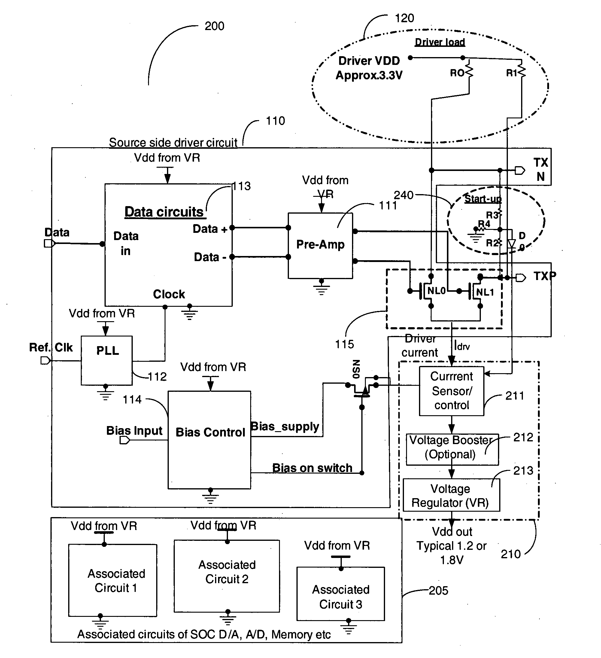
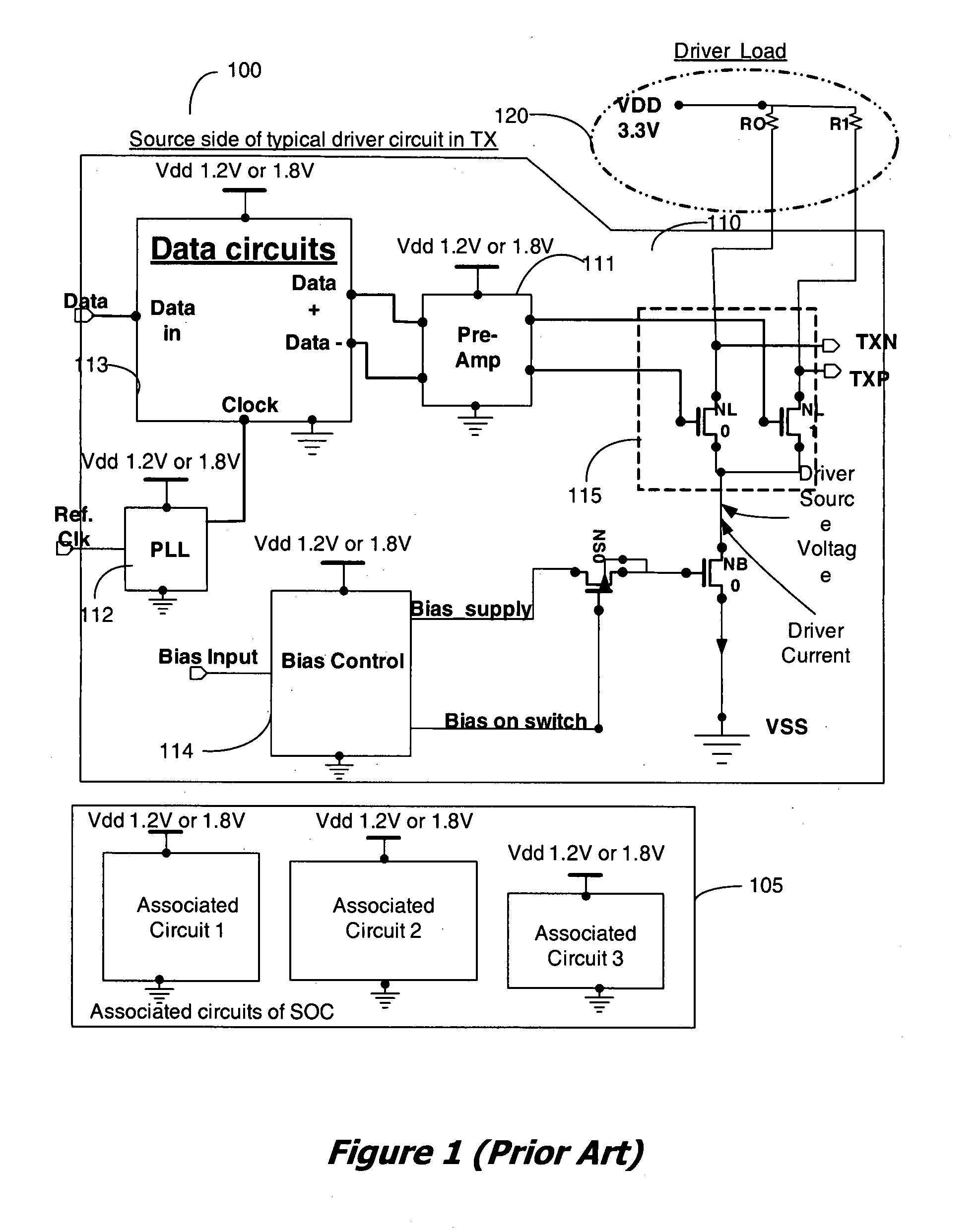
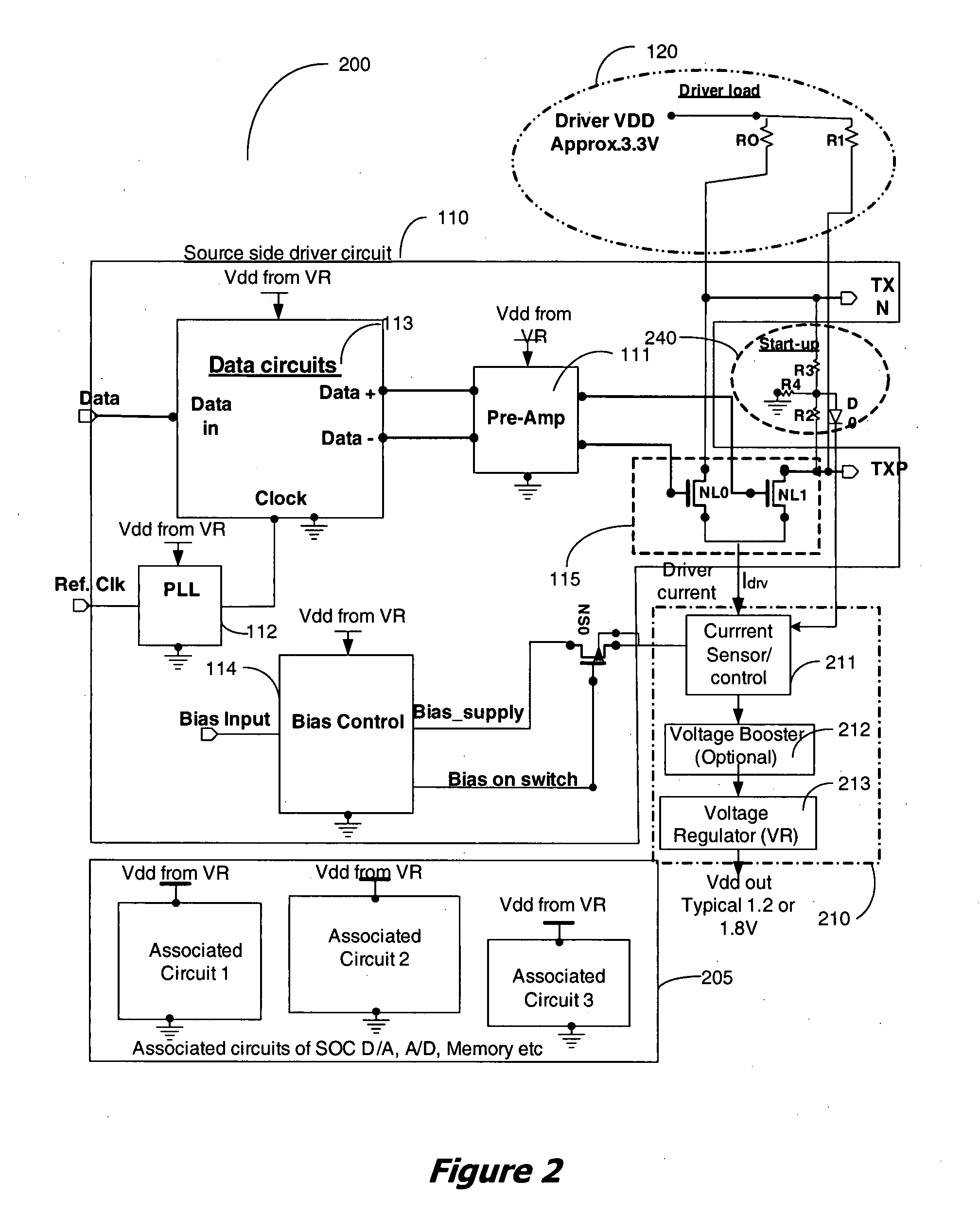
[0013]An apparatus and method for supplying power to integrated circuits (ICs) of a system implemented as a system on a chip, (SOC) from the wasted power in low-swing high-speed differential line drivers used in the system, is disclosed. In a high speed line driver the load resistors of the driver are connected to a power supply, either the local power supply or the remote receiver power supply. DC power for the driver is supplied through these resistors. A large portion of this power, supplied from the power supply is wasted in the DC set-up circuit of the differential line driver. It is proposed to use this wasted power to power selected circuits of the ICs in the system. The use of this wasted power from the drivers for powering the circuits reduces the overall power dissipation of the system. The disclosed apparatus and method are applicable for integrated circuit (IC), a system on chip (SOC), chip on board (COB) implementations and other system and circuit level implementations...


PUM


Abstract

An apparatus and method for supplying power to circuits of an integrated circuit (IC) from the wasted power in low-swing high-speed differential line drivers used in the IC, is disclosed. In a high speed line driver the load resistors of the driver are connected to a power supply, either the local power supply or the receiver power supply. DC power for the driver is supplied through these resistors. A large portion of this power, supplied from the power supply is wasted in the DC set-up circuit of the differential line driver. It is proposed to use this wasted power to power selected circuits of an IC. The use of this wasted power from the drivers for powering the circuits reduces the overall power dissipation of the system.

Description

CROSS-REFERENCE TO RELATED APPLICATION[0001]This application is a continuation-in-part of U.S. patent application Ser. No. 11 / 800,861 filed May 7, 2007.BACKGROUND OF THE INVENTION[0002]1. Field of the Invention[0003]The invention generally relates to the powering of circuit blocks and devices in a system implemented as an integrated circuit, system on a chip or a chip on board using the wasted power from low swing, high speed differential driver supply.[0004]2. Prior Art[0005]A typical data processing and transmitting system 100 is shown in FIG. 1. The system shows a typical system on chip (SOC) implementation of data processing circuits with differential drivers, their peripheral circuits 110, and a set of associated circuit blocks 105. The associated circuits 105 include integrated circuits like memory, digital-to-analog converter (DAC), analog-to-digital converter (ADC), clock circuits, and other circuits that make up the SOC 100. It also shows a termination load circuit 120 that...

Claims


Application Information

Patent Timeline
Patent Type & Authority Applications(United States)
IPC IPC(8): G05F3/02
CPCH03F3/45183H03F2203/45008H03F2203/45466H03F2203/45506H03F2203/45654H03F2203/45696H03K19/0019H04L25/0264H04L25/0272H04L25/028
Inventor CHI, HONGWU
Owner ANALOGIX SEMICON
Why Eureka
Try Eureka