Optical Disc, Optical Disc Driving Apparatus, Optical Disc Driving Method, Data Processing Apparatus, and Optical Disc Recording/Reproducing Apparatus

a technology for optical discs and drives, applied in the field of optical discs, can solve problems such as the inability to carry out recording or reproducing control suitable for optical discs, the information about physical properties itself may be unreadable, and the problem of special pronounced problems

Active Publication Date: 2008-11-13
MITSUBISHI ELECTRIC CORP
View PDF16 Cites 39 Cited by
  • Summary
  • Abstract
  • Description
  • Claims
  • Application Information

AI Technical Summary

Benefits of technology

[0010]According to the present invention, optical control that prevents an optical disc driving appara

Problems solved by technology

Although information about the physical properties is recorded in the subcode in the prior art noted above, when the difference in physical properties includes a difference in recording density, the information about the physical properties may itself be unreadable, in which case recording or reproducing control suitable for the optical disc cannot be carried out.
This problem is particularly pronounced in the hybrid optical discs proposed as next-generation discs, in which a single disc includes both a standard-density recording area and a high-density recording area.
In this type

Method used


Image

  • Optical Disc, Optical Disc Driving Apparatus, Optical Disc Driving Method, Data Processing Apparatus, and Optical Disc Recording/Reproducing Apparatus
  • Optical Disc, Optical Disc Driving Apparatus, Optical Disc Driving Method, Data Processing Apparatus, and Optical Disc Recording/Reproducing Apparatus
  • Optical Disc, Optical Disc Driving Apparatus, Optical Disc Driving Method, Data Processing Apparatus, and Optical Disc Recording/Reproducing Apparatus

Examples


first embodiment

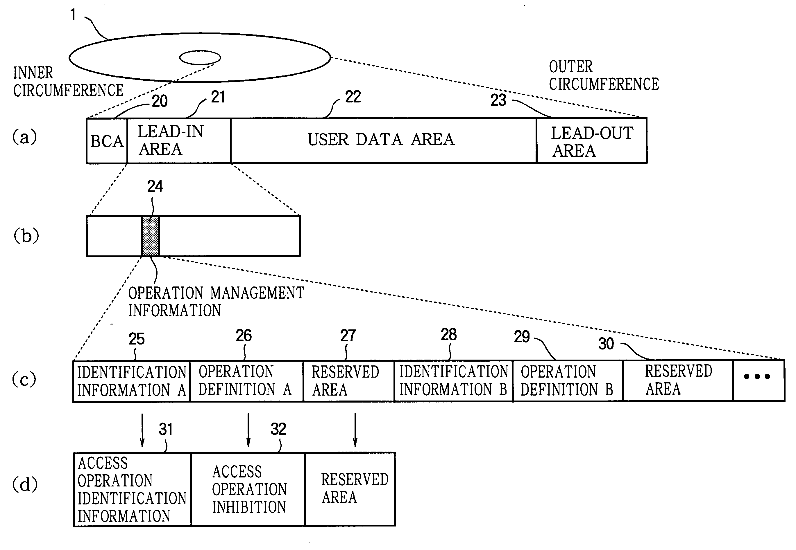
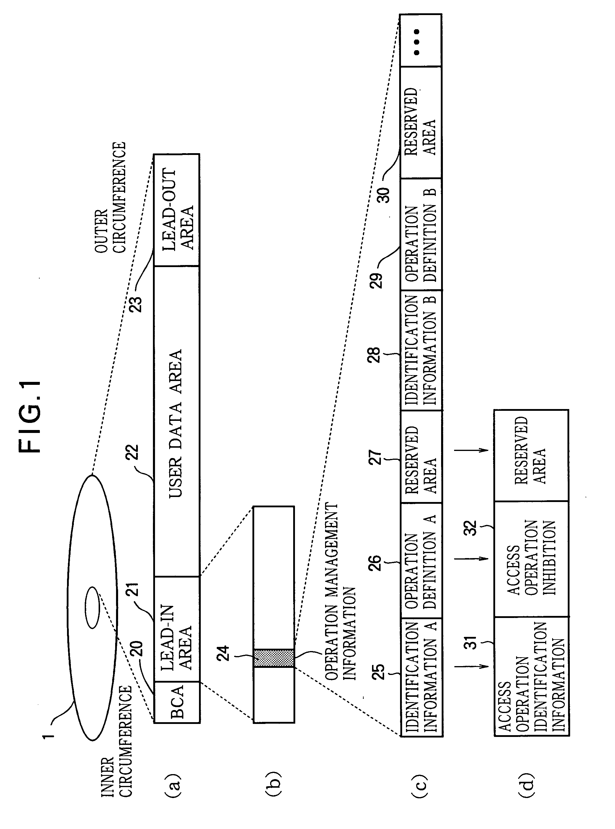
[0033]FIG. 1 is a drawing showing the recording area format of an optical disc in a first embodiment. As shown in FIG. 1 (a), from its inner edge to its outer edge, the optical disc 1 comprises a BCA (Burst Cutting Area) 20 in which information is recorded when the fabrication of the optical disc 1 has been completed, a lead-in area 21 in which information about the physical properties of the optical disc 1 is recorded, a user data area 22 in which content data are recorded, and a lead-out area 23 in which the same information is recorded as in the lead-in area 21. Reproduction by the optical disc driving apparatus proceeds sequentially-outward from the inner circumference of the optical disc 1.

[0034]As shown in FIG. 1 (b), operation management information 24 for management and control of the operation of the optical disc driving apparatus that reproduces signals from the optical disc 1 is recorded in the lead-in area 21.

[0035]FIG. 1 (c) shows the recording format of the operation m...

second embodiment

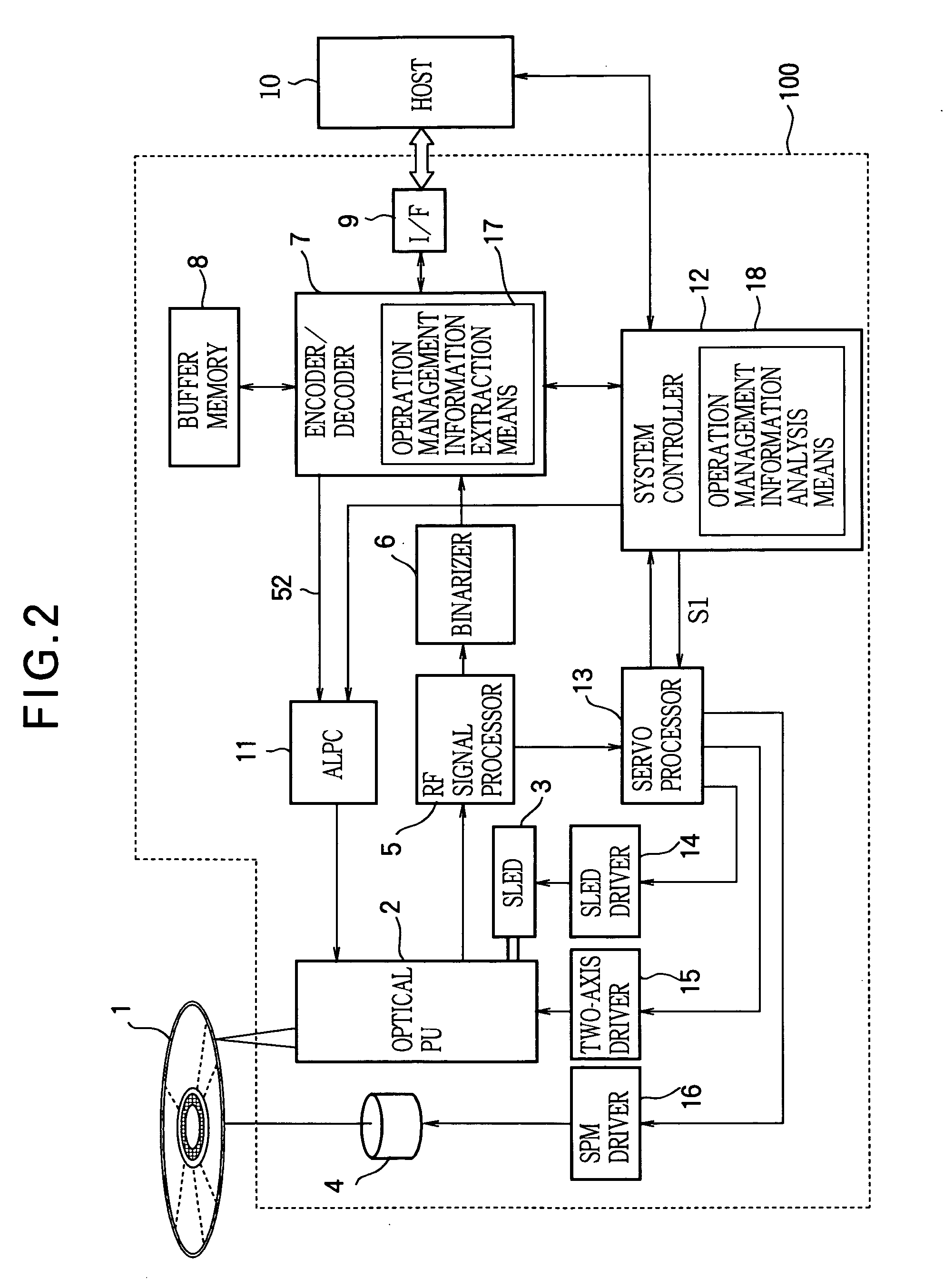
[0041]FIG. 2 is a block diagram of an optical disc driving apparatus 100 for the optical disc in the first embodiment.

[0042]As shown in FIG. 2, the optical disc 1 is read by an optical pick-up (PU) 2, followed by amplification in an RF signal processor 5. The RF signal processor 5 outputs a reproduced-RF signal to a binarizer 6, and generates a tracking error signal, a focus error signal, and other signals which are supplied to a servo processor 13 for servo control.

[0043]The servo processor 13 generates a focus drive signal and a tracking drive signal responsive to the focus error signal and tracking error signal, and supplies them to a two-axis driver 15. The two-axis driver 15 performs focus and tracking control by driving a focus coil and a tracking coil in the optical pickup 2.

[0044]Seek access to a desired address is carried out as follows. The servo processor 13 generates a sled control signal according to a sled error signal obtained as a low-frequency component of the track...

third embodiment

[0057]The flow of operations when the optical disc 1 of the first embodiment is loaded into the optical disc driving apparatus 100 will be described with reference to FIG. 3.

[0058]When the optical disc 1 is loaded into the optical disc driving apparatus 100, the optical disc driving apparatus 100 executes a starting operation sequence in which, without relying on commands from the host 10, it automatically carries out various adjustments while obtaining various information from the optical disc 1. In the starting operation sequence, the operation management information extraction means 17 in the optical disc driving apparatus 100 obtains the operation management information 24 from the optical disc 1 and extracts the access operation identification information 31 (ST11), and the operation management information analysis means 18 decides whether the extracted information matches stored identification information (ST12). If the access operation identification information 31 matches, t...


PUM


Abstract

By avoiding the problem that in a hybrid optical disc with a standard-density recording area and a high-density recording area, an optical pickup designed to be suitable for the standard-density recording area cannot operate as desired in the high-density recording area and may cause a malfunction, damage to the disc drive or optical disc is prevented and optimal control is enabled. Access operation identification information such as reproducing identification information 225 indicating whether or not information recorded in the user data area 222 of the optical disc can be reproduced under the reproducing conditions of the optical disc driving apparatus is recorded in the lead-in area 222. The optical disc driving apparatus reads this type of access operation identification information, compares it with access operation identification information possessed by the optical disc driving apparatus, and if they do not correspond, does not carry out access operations by the optical head to the user data area 222, because reproducing or recording compatibility with the optical disc 201 is lacking.

Description

FIELD OF THE INVENTION[0001]The present invention relates to an optical disc such as any of the various types of DVD discs, including DVD-ROM (Digital Versatile Disc Read Only Memory), DVD-R (Recordable), and DVD-RW (Rewritable); the invention also relates to optical disc driving apparatus and an optical disc driving method that operate according to information recorded in these optical discs, to data processing apparatus connected to the optical disc driving apparatus, to optical disc recording apparatus or reproducing apparatus equipped with the optical disc driving apparatus (apparatus that can perform at least one of the two operations of recording on and reproducing from an optical disc will also be referred to as ‘optical disc recording / reproducing apparatus’), to optical discs for operational testing, and to an operational test method.BACKGROUND ART[0002]As technology for enabling the physical properties of discs and unit areas to be distinguished easily and accurately while ...

Claims


Application Information

Patent Timeline
IPC IPC(8): G11B7/24G11B7/004G11B7/007G11B19/04
CPCG11B7/00736G11B7/0079G11B19/04G11B20/1217G11B20/1262G11B2020/1229G11B2020/1278G11B2020/1285G11B2220/2583
Inventor YASHIMA, NOBORUKIZU, NAOKIISHIZUKA, MITSURUMICHIHATA, SATOSHIKIYOSE, YOSHIHIROTSUKAHARA, OSAMUOGAWA, MASAHARU
Owner MITSUBISHI ELECTRIC CORP
Why Eureka
Try Eureka