
Formation of catalytic regions within porous structures using supercritical phase processing

a technology of supercritical phase and catalytic regions, which is applied in the direction of physical/chemical process catalysts, lighting and heating apparatus, prosthesis, etc., can solve the problems of microporous structures, sieves, and inability to form arbitrary materials into a selected microporous structur

Inactive Publication Date: 2008-11-13
UMICORE AG & CO KG +1
View PDF121 Cites 61 Cited by
  • Summary
  • Abstract
  • Description
  • Claims
  • Application Information

AI Technical Summary

Benefits of technology

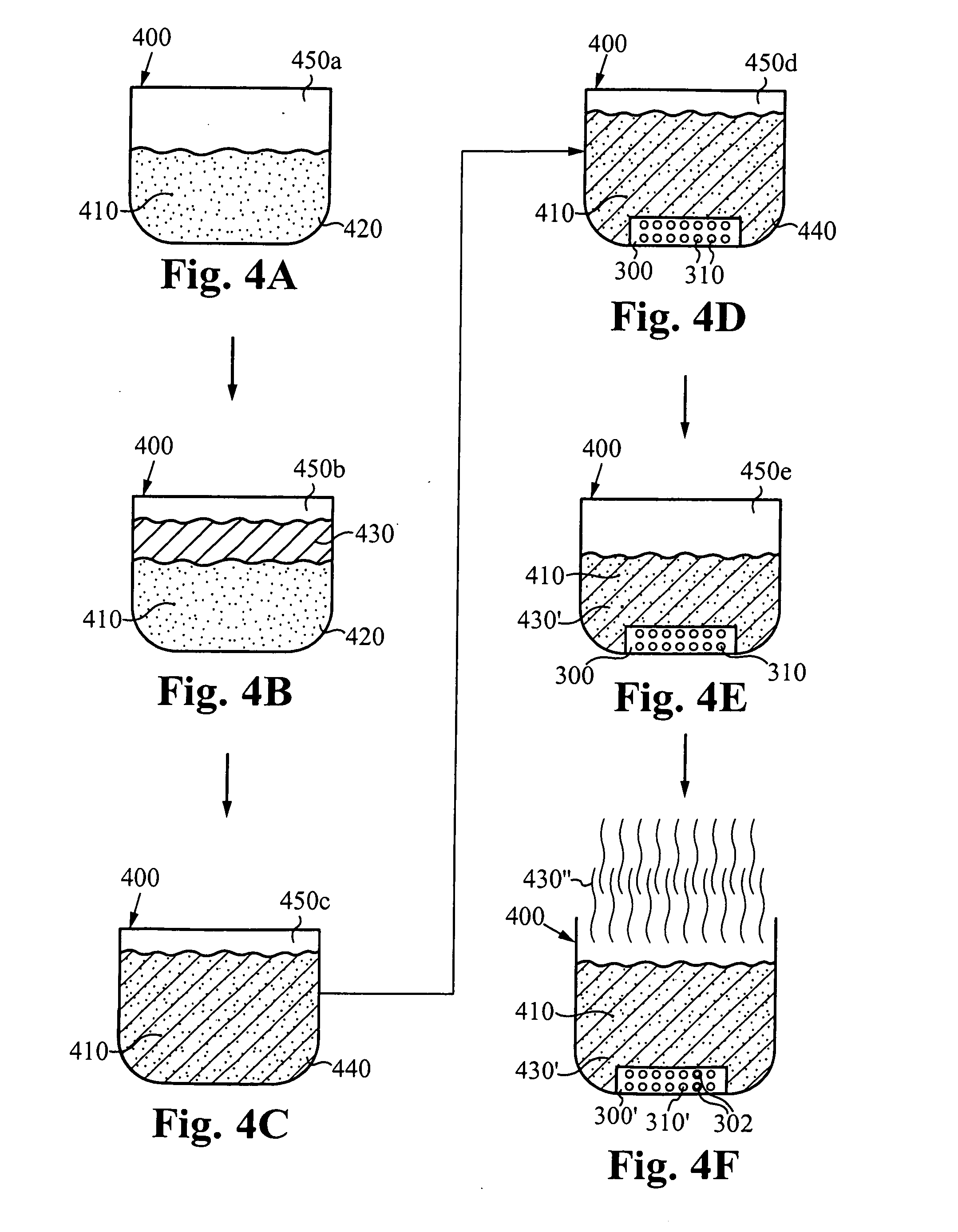
[0010]In another aspect of the present invention, a method of forming a catalytic region on a microporous structure is disclosed. The microporous structure has an exterior surface and a plurality of pores. In the method, a plurality of particles is dispersed within a carrier fluid, thereby forming a carrier mixture. A supercritical fluid is mixed with the carrier mixture, thereby forming a heterogeneous mixture. The carrier fluid is then removed from the heterogeneous mixture, thereby forming a supercritical dispersion. The supercritical dispersion comprises the plurality of particles dispersed in the supercritical fluid. The microporous structure is exposed to the supercritical dispersion. Finally, the supercritical fluid is removed from the supercritical dispersion while the supercritical dispersion is in contact with the porous structure, thereby depositing the plurality of particles from the supercritical dispersion onto the microporous structure. The deposited particles are catalytic, thereby enabling the formation of one or more catalytic regions on the porous structure.

Problems solved by technology

Some microporous structures, for example some molecular sieves, do not provide for chemical catalysis, but instead solely accomplish physical modulation of working fluids or solutions.
Unfortunately, because these production methods and formation mechanisms can operate only on materials with chemical structure, arbitrary materials cannot be formed into a selected microporous structure.
Additionally, the catalytic mechanisms within microporous structures are complex and do not always directly relate to the catalytic functionality present in precursors.

Method used


Image

  • Formation of catalytic regions within porous structures using supercritical phase processing
  • Formation of catalytic regions within porous structures using supercritical phase processing
  • Formation of catalytic regions within porous structures using supercritical phase processing

Examples


Embodiment Construction

[0019]The description below concerns several embodiments of the invention. The discussion references the illustrated preferred embodiment. However, the scope of the present invention is not limited to either the illustrated embodiment, nor is it limited to those discussed, to the contrary, the scope should be interpreted as broadly as possible based on the language of the Claims section of this document.

[0020]This disclosure refers to both particles and powders. These two terms are equivalent, except for the caveat that a singular “powder” refers to a collection of particles. The present invention may apply to a wide variety of powders and particles.

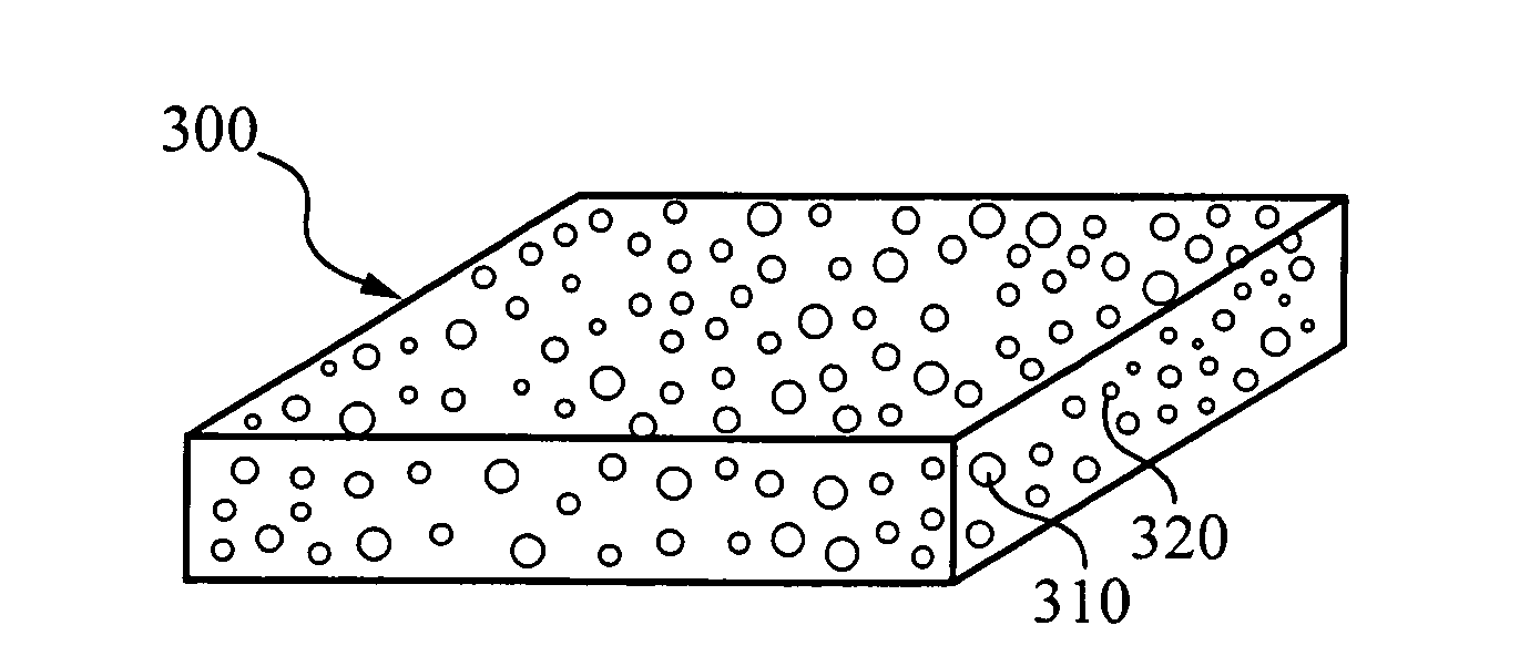
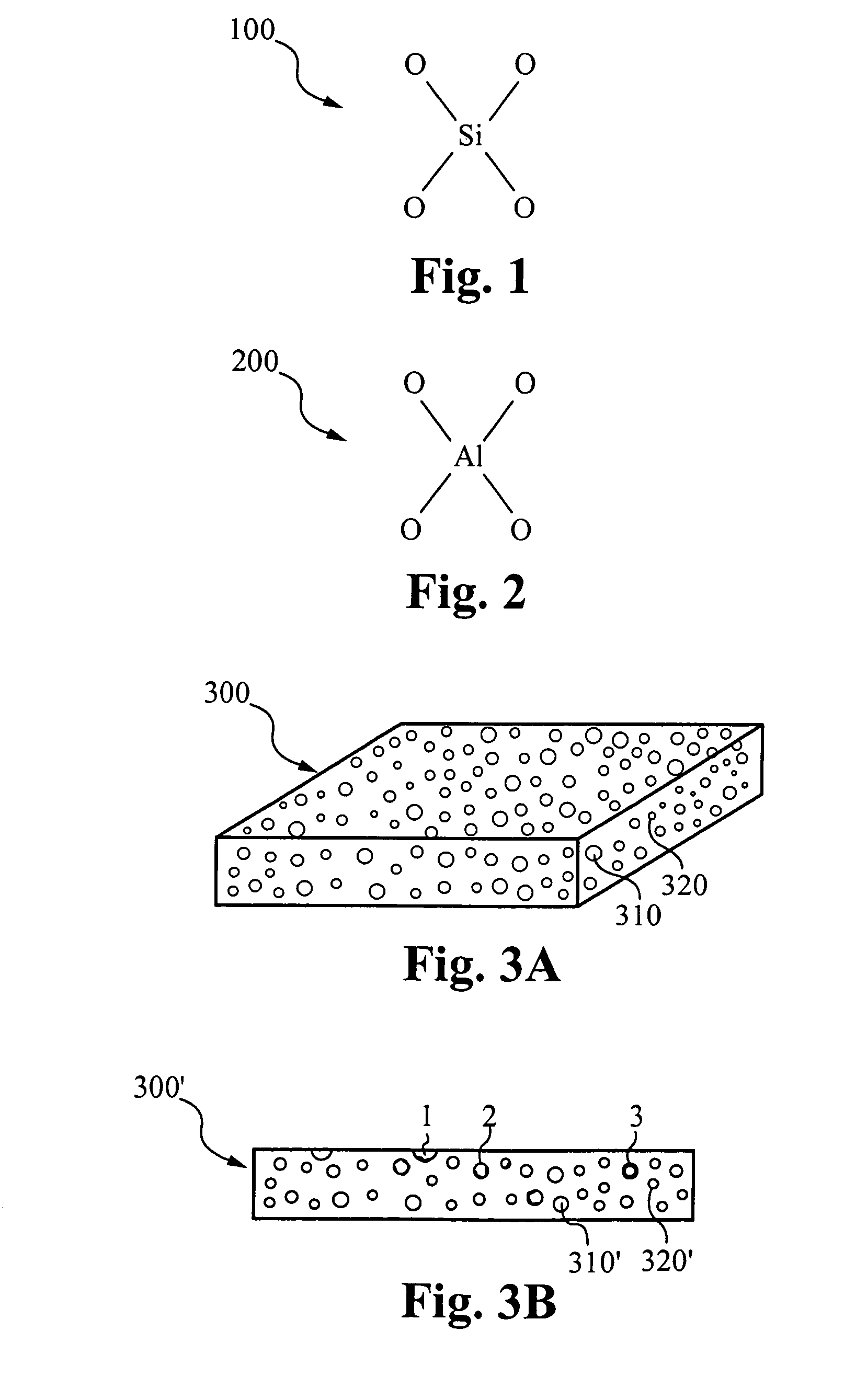
[0021]For the purposes of this disclosure, a microporous structure is a structure having a plurality of very fine pores. In one embodiment, a microporous structure comprises a plurality of pores having an average pore diameter of less than 1 micron. In another embodiment, the microporous structure comprises a plurality of pores having an...


PUM

PropertyMeasurementUnit
Grain sizeaaaaaaaaaa
Pore sizeaaaaaaaaaa
Pore sizeaaaaaaaaaa

Abstract

A method of forming a catalytic region on a porous structure having an exterior surface and a plurality of pores, the method comprising: forming a supercritical dispersion, wherein the supercritical dispersion comprises a plurality of particles dispersed in a supercritical fluid; exposing the porous structure to the supercritical dispersion; and depositing the plurality of particles from the supercritical dispersion onto the porous structure, wherein each one of the deposited plurality of particles is catalytic, thereby forming one or more catalytic regions on the porous structure. The method is particularly well suited for creating catalytic regions within pre-formed microporous structures.

Description

CROSS-REFERENCE TO RELATED APPLICATIONS[0001]The present application claims priority to co-pending U.S. Provisional Application Ser. No. 60 / 928,946, filed May 11, 2007, entitled “MATERIAL PRODUCTION SYSTEM AND METHOD,” which is hereby incorporated by reference as if set forth herein.FIELD OF THE INVENTION[0002]The present invention relates to systems and methods of forming catalytic regions within porous structures. More particularly, the present invention relates to supercritical phase processing of powders to form catalytic regions within porous structures.BACKGROUND OF THE INVENTION[0003]Certain microporous structures can serve as valuable industrial catalysts. Several features of these structures make them particularly well suited for catalytic applications. For example, their high surface area to volume ratio provides a dense region of reactivity. Their heterogeneity with fluid reactants and products permits relatively easy recovery of the catalyst post-reaction. Furthermore, t...

Claims


Application Information

Patent Timeline
IPC IPC(8): B05D3/02
CPCB22F9/12Y10T156/15F28D7/024F28D7/08F28D15/00F28F27/00B22F2999/00B01J19/0013Y10S623/923B01J25/00B01J25/02Y10S623/92B22F2202/13Y10T137/0391Y10T137/2076A61L2/18B22F2203/13B01J19/088B01J37/0018B01J37/349B01J37/06B01J2219/0805B01J2219/0894B01J35/56B01J2/16B01J37/0027B01J2219/0879F28C3/16
Inventor KEVWITCH, ROBBIBERGER, MAXIMILIAN A.
Owner UMICORE AG & CO KG
Learn More