
Position Determination of Mobile Stations in a Wireless Network

Active Publication Date: 2008-11-13
TAIWAN SEMICON MFG CO LTD
View PDF23 Cites 55 Cited by
  • Summary
  • Abstract
  • Description
  • Claims
  • Application Information

AI Technical Summary

Benefits of technology

[0020]The acceptance or rejection of said updated timing data at any station may be determined in response to a cumulative error function calculated in respect of the transmission of such data, relative to other prior or simultaneous transmissions of such data received at said station, thereby maintaining a high level of accuracy in respect of the synchronization of clocks at each station of the network.
[0062]The network may include a central authority to define probe channels for the transmission of the probe signals, to reduce interference and prevent jamming or interception of the signals.

Problems solved by technology

At present it is difficult to locate certain of these devices, such as in the VOIP (Voice Over Internet Protocol) environment, without using positioning equipment together with the wireless unit as there is no fixed relationship between the VOIP device and the geographic position.
In addition, positioning technologies are subject to limitations that may render the stations undetectable.

Method used


Image

  • Position Determination of Mobile Stations in a Wireless Network
  • Position Determination of Mobile Stations in a Wireless Network
  • Position Determination of Mobile Stations in a Wireless Network

Examples


first embodiment

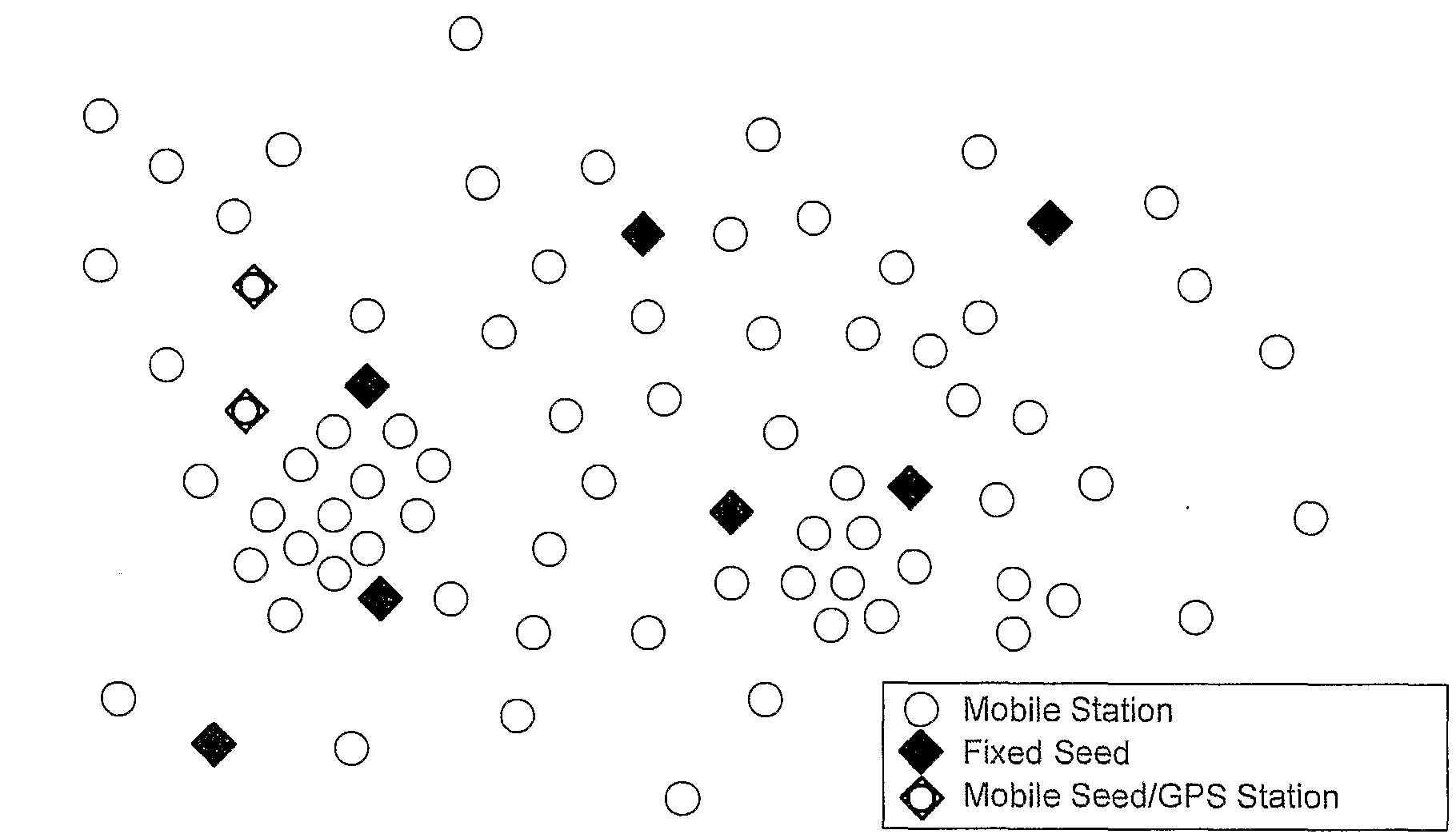
[0154]FIG. 3 shows the same network illustrated in FIG. 2 over time. At time t0 (as shown in FIG. 3(a)), none of the wireless mobile stations in an area have location information from the network. However, there are several fixed seeds interspersed throughout the area and there are also some mobile seeds, or mobile stations that have independent positioning systems. At time t1 (FIG. 3(b)) several stations have successfully developed position information from the seeds and the stations with known positions according to the invention. Notably, stations in more densely populated areas determine some form of position (relative or absolute) more quickly. In FIG. 3(c) many of the stations that had only determined relative position before now have neighbors with absolute position that enables these relative positions to very quickly become absolute.

second embodiment

[0155]FIG. 3(d) shows time t1 for position determination according to the invention. Here only absolute position is determined. As more and more stations are able to establish their positions, other neighboring stations will also be able to determine their own positions and the number of stations with known positions will grow iteratively and exponentially as is shown at time t2 (FIG. 3(e)).

[0156]In both of the illustrated crystallization mechanisms illustrated, ultimately, all of the stations on the network that are able to locate neighbors will be capable of establishing position to a greater or lesser degree of accuracy—then reassessing information and refining position as updated or alternative information is made available. Even lonely neighbors, unable to develop the minimum number of neighbors, may be provided with information from the other stations to establish their position (unless completely outside propagation range). However, depending on the distance, the quality of i...


PUM


Abstract

A network, and a method of operating a network. The network includes a plurality of stations each able to transmit and receive data so that the network can transmit data between stations via at least one selected intermediate station. Each station transmits probe signals in broadcast fashion to other stations to gather a list of neighbour stations. The stations transmit position data and / or position determining data in at least some of the probe signals. Each station maintains position data and / or position determining data received from selected probing stations, and utilizes the data to determine the absolute or relative position of itself and / or other stations. The stations can determine the relative or absolute position of other stations in direct communication with themselves, and also of other stations not in direct communication with themselves.

Description

BACKGROUND OF THE INVENTION[0001]This invention relates to a method of locating and determining the position of wireless mobile stations in a communication network. For the purposes of this specification, such a communication network will be referred to as an Opportunity Driven Multiple Access (ODMA) network.[0002]The determination of location is useful to service providers in the provision of location based services to subscribers to a communication network. Such services include, for example, the provision of driving direction instructions, vehicle tracking, relevant regional information and available applications; while also enabling categorization of subscribers for various purposes and for billing differentiation.[0003]In addition, various regulatory authorities around the world now require that service providers of wireless telephone networks must be capable of locating the users of the wireless telephones in order to facilitate emergency call processing.[0004]These regulation...

Claims


Application Information

Patent Timeline
IPC IPC(8): H04Q7/20H04W4/02H04W4/029H04W8/14H04W56/00H04W64/00
CPCG01S5/0226G01S5/0289G01S5/14H04B7/2606H04W4/02H04L69/28H04W8/14H04W56/0015H04W64/00H04W64/006H04L67/18H04W4/023H04L67/52H04W4/029
Inventor LARSEN, JAMES DAVID
Owner TAIWAN SEMICON MFG CO LTD
Learn More