
Digital Mixing System With Dual Consoles and Cascade Engines

a digital mixing system and cascade engine technology, applied in broadcast information generation, redundant hardware error correction, instruments, etc., can solve the problem that the mixing system cannot immediately perform the instructed recall processing, the scene recall execution timing is lag, and the technology is not available by, so as to improve the throughput and reduce the cost , the effect of high independency

Inactive Publication Date: 2008-11-13
YAMAHA CORP
View PDF12 Cites 13 Cited by
  • Summary
  • Abstract
  • Description
  • Claims
  • Application Information

AI Technical Summary

Benefits of technology

The present invention provides a mixing system control method that can synchronize multiple mixing systems in a correct timing relation. The method allows for optimal communication environments based on the installation conditions of consoles and other equipment. The method also enhances the throughput of the mixing system by using a plurality of mixing systems with a low-cost configuration. The invention also provides a mixing system control apparatus and program for carrying out the method. The technical effects of the invention include improved communication between mixing systems and increased flexibility for operators.

Problems solved by technology

However, if any of these other systems is performing a top-priority processing operation of its own, such a mixing system cannot immediately perform the instructed recall processing.
If this happens, there occurs a problem of a time lag in scene recall execution timing between the mixing systems concerned.
However, no technologies are available by which the control state of volume level can be freely set for each of the operators in accordance with console installation conditions.
This configuration makes it impossible to obtain an independent mixing result in each of a plurality of cascaded mixing systems.
Likewise, if cue signals in the cascaded mixing systems are mixed over a plurality of stages, the final cue signal can be obtained only in the rearmost mixing system (cascade master), so that it is also difficult to obtain an independent final cue signal in each of the cascaded systems.
However, if an operation event occurs such as a scene recall which involves large amounts of data to be transmitted at a time, a problem is caused that a time lag in the operation timing between the two consoles occurs due to the transmission delay of the data.
On the other hand, if a communication path fast enough for transmitting the data between the two consoles without delay is arranged, the time lag in the operation timing is mitigated, but at the expense of an increased cost.
However, the prior-art mixing systems are not adapted to such a mode of operations, thereby presenting problems that it is difficult to monitor a plurality of systems, and the operation by one operator affects the monitoring by another operator, for example.

Method used


Image

  • Digital Mixing System With Dual Consoles and Cascade Engines
  • Digital Mixing System With Dual Consoles and Cascade Engines
  • Digital Mixing System With Dual Consoles and Cascade Engines

Examples


Embodiment Construction

1. Hardware Configurations of Embodiments

1.1 Console

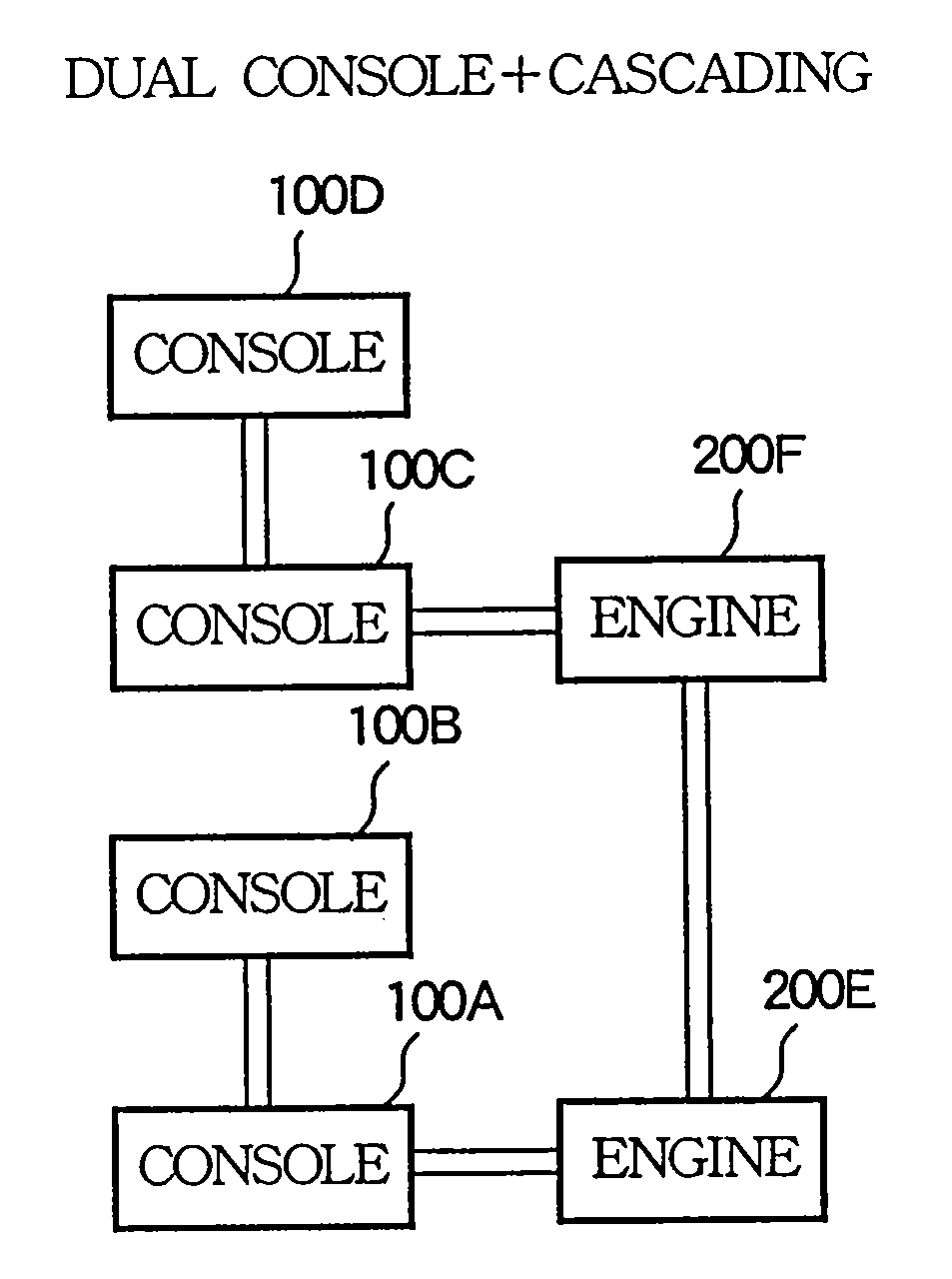
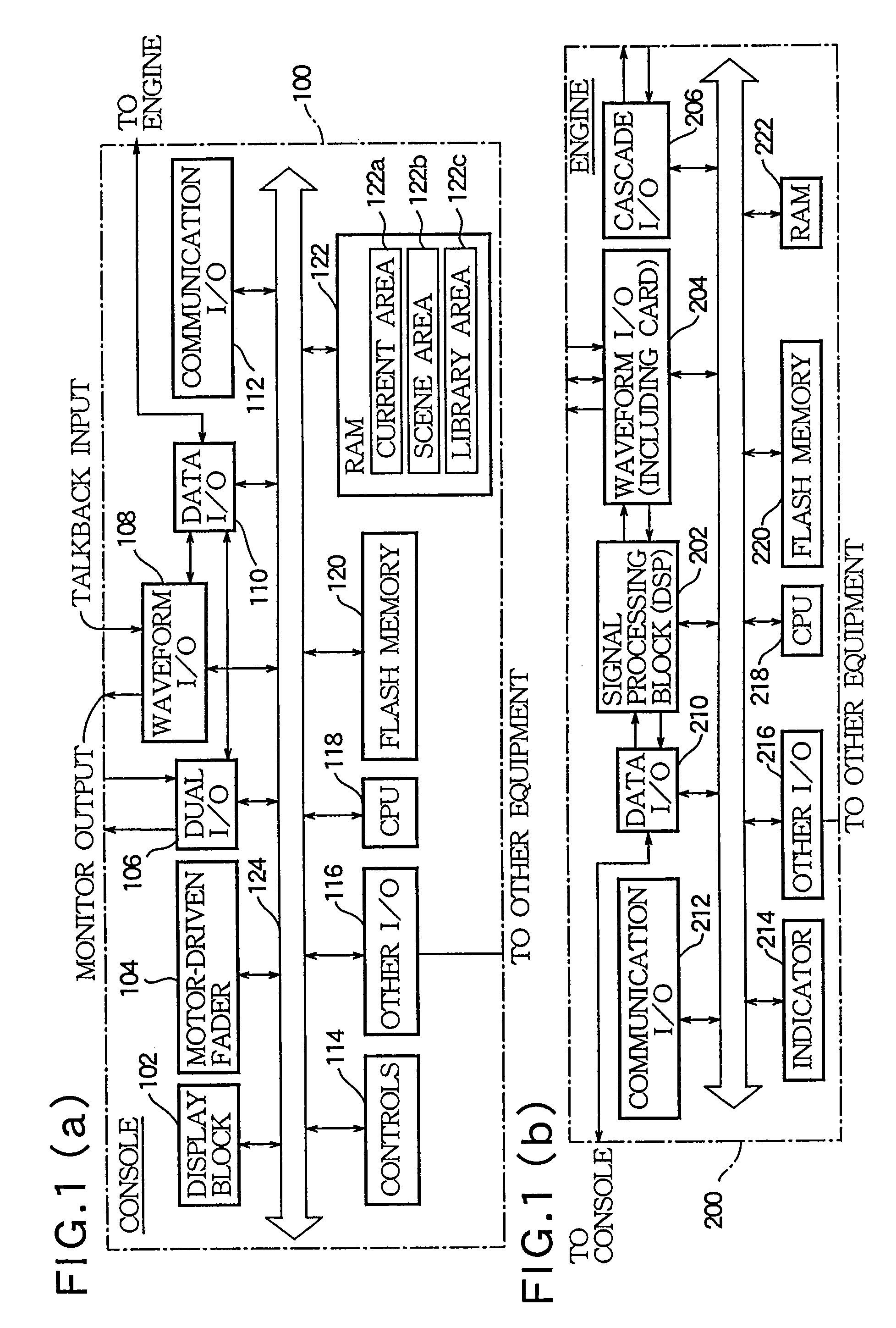
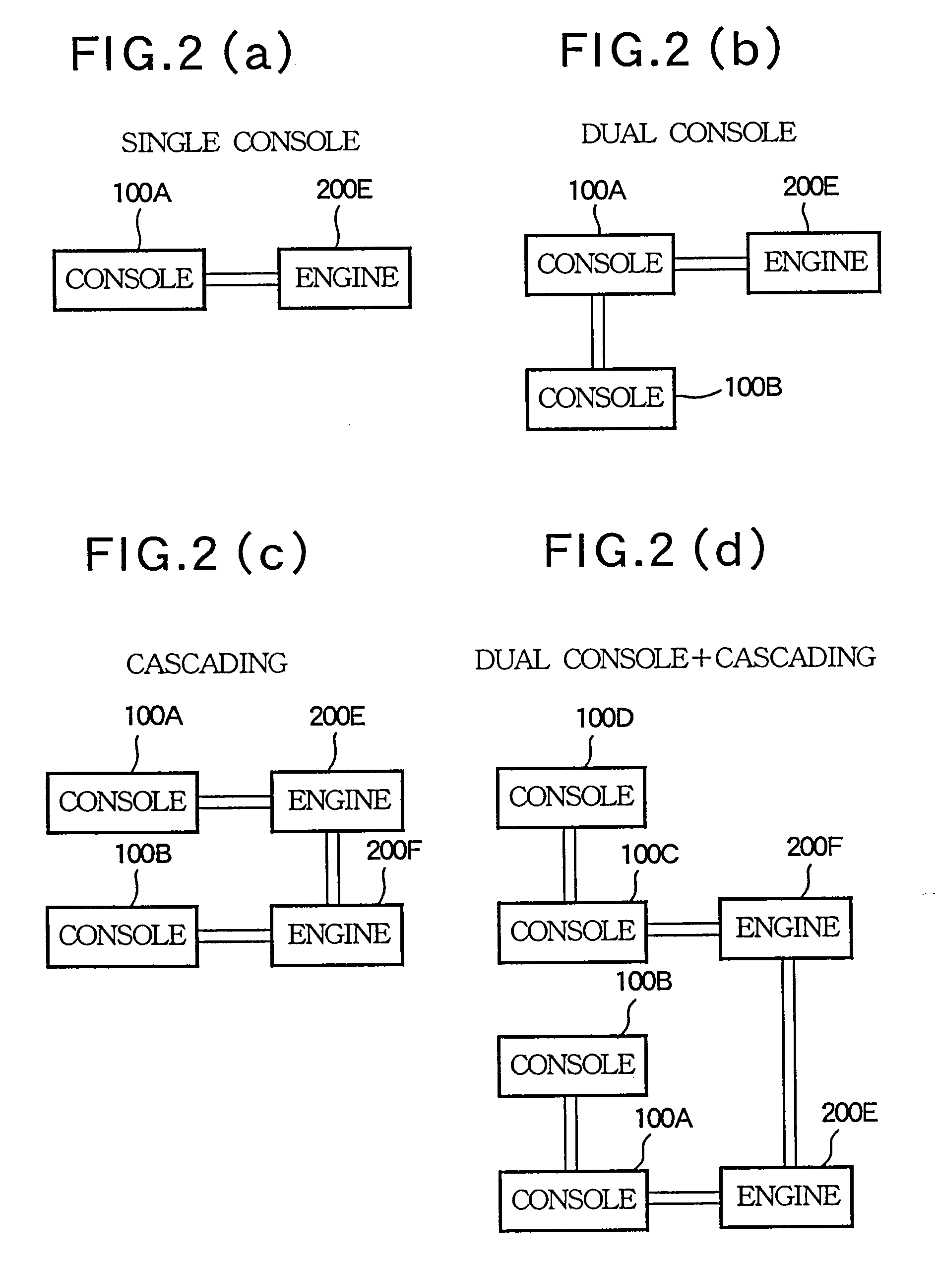
[0055]The following describes a digital mixing system practiced as one embodiment of the invention. This embodiment comprises one or more consoles 100 and one or more engines 200. First, the hardware configuration of the console 100 is described with reference to FIG. 1(a).

[0056]In the figure, reference numeral 102 denotes an indicator, which displays various information for the operator of the console 100 to perform various operations. Reference numeral 104 denotes motor-driven fader block which is constituted by “48” motor-driven faders. These faders are operated by the operator or automatically if required on the basis of the scene data for example stored in the console 100.

[0057]Reference numeral 114 denotes a controls group which is constituted by various controls for adjusting the tone qualities for example of audio signals. These controls are also operated by the operator or automatically if required on the basis of the data...


PUM


Abstract

A method is designed for controlling a total mixing system including a first mixing system and a second mixing system, which are operated in a linked manner. In the method, the first mixing system stores first scene data specifying contents of a mixing process matching a scene. The second mixing system stores second scene data specifying contents of a mixing process matching a scene. The first mixing system transmits a scene recall request to the second mixing system when a recall event of the first scene data occurs. The second mixing system transmits back a recall enabling response to the first mixing system after receipt of the scene recall request. The first mixing system reconstructs the contents of the mixing process on the basis of the first scene data after the reception of the recall enabling response. The second mixing system reconstructs the contents of the mixing process on the basis of the second scene data after the transmission of the recall enabling response.

Description

CROSS-REFERENCE TO RELATED APPLICATIONS[0001]This application is a division of U.S. patent application Ser. No. 10 / 626,358 filed Jul. 24, 2003, the entire disclosure of which is incorporated herein by reference.BACKGROUND OF THE INVENTION[0002]1. Technical Field of the Invention[0003]The present invention relates generally to a mixing system control method, a mixing system control apparatus, and a mixing system control program, which are suitably used for a large-scale mixing system.[0004]2. Prior Art[0005]Recently, digital mixing systems have come into widespread use, especially in the field of professional-use sound equipment. In these systems, sound signals picked up by microphones are all converted into digital signals, which are mixed in a mixing engine constituted by a DSP array and so on. With large-scale digital mixing systems, the mixing console operated by a user and the mixing engine are often separated from each other.[0006]For example, the mixing console is installed at...

Claims


Application Information

Patent Timeline
Patent Type & Authority Applications(United States)
IPC IPC(8): G06F17/00G06F11/07G06F11/16G06F3/048H04H60/04
CPCH04H60/04
Inventor AOKI, TAKAMITSUNAKAYAMAI, KEI
Owner YAMAHA CORP
Learn More