Method for controlling combined lathe apparatus, combined lathe apparatus, turning tool holder, blade position registering apparatus, and blade position detecting apparatus

a combined lathe and detecting device technology, applied in direction finders using radio waves, instruments, manufacturing tools, etc., can solve the problems of small space for installing machine tools within a factory, poor precision of processing workpieces, and workpieces due to their own weight directly affecting process precision (cylindricity), etc., to suppress the effect of workpiece bending

Inactive Publication Date: 2008-11-20
YAMAZAKI MAZAK KK
View PDF93 Cites 18 Cited by
  • Summary
  • Abstract
  • Description
  • Claims
  • Application Information

AI Technical Summary

Benefits of technology

[0017]An objective of the present invention is to provide a method for controlling a combined lathe apparatus having automatic tool replacing means, which method suppresses the effects of a workpiece bending due to its own weight, the effects of pitching due to a change in the manner in which the bed having a low rigidity bends in the vertical direction, and the effects of thermal displacement due to heat from a motor and bearings for rotating a rotating tool.
[0018]Another object of the present invention is to provide a combined lathe apparatus having automatic tool replacing means, which apparatus suppresses the effects of a workpiece bending due to its own weight, the effects of pitching due to a change in the manner in which the bed having low rigidity bends in the vertical direction, and the effects of thermal displacement due to heat from a motor and bearings for rotating a rotating tool.

Problems solved by technology

2) The space for installing the machine tool within a factory is small.
In the case where a turning process is carried out on the outer peripheral surface of a workpiece in the above described combined lathe apparatus having automatic tool replacing means, a problem arises that bending of the workpiece due to its own weight directly affects the process precision (cylindricity).
Accordingly, when a turning process is carried out at a predetermined angle θ relative to the horizontal line Yt, it is subjected to the effects of the workpiece bending, and therefore the precision of processing the workpiece becomes poor (hereinafter this problem is referred to as first problem).
However, the location of the base changes and the load applied to the jack bolt also changes because of the occurrence of an earthquake, a change in the state of the base made of concrete on which the machine tool is installed and the like.
This error affects the position of the blade in the vertical direction and at the same time affects the precision of processing the workpiece W (hereinafter this problem is referred to as second problem).
In the case where this problem is addressed by readjusting the jack bolt, a great amount of time and effort are required for the adjustment.
In addition to this, it is difficult to determine whether or not the change in the state of the base has lowered the precision.
In accordance with this technology, however, no fundamental measure is taken against the problem and therefore it is difficult to stably carry out a turning process with high precision.

Method used


Image

  • Method for controlling combined lathe apparatus, combined lathe apparatus, turning tool holder, blade position registering apparatus, and blade position detecting apparatus
  • Method for controlling combined lathe apparatus, combined lathe apparatus, turning tool holder, blade position registering apparatus, and blade position detecting apparatus
  • Method for controlling combined lathe apparatus, combined lathe apparatus, turning tool holder, blade position registering apparatus, and blade position detecting apparatus

Examples


first embodiment

[0047]In the following, a combined lathe apparatus and a turning tool holder according to one embodiment of the present invention are described with reference to FIGS. 1 to 7.

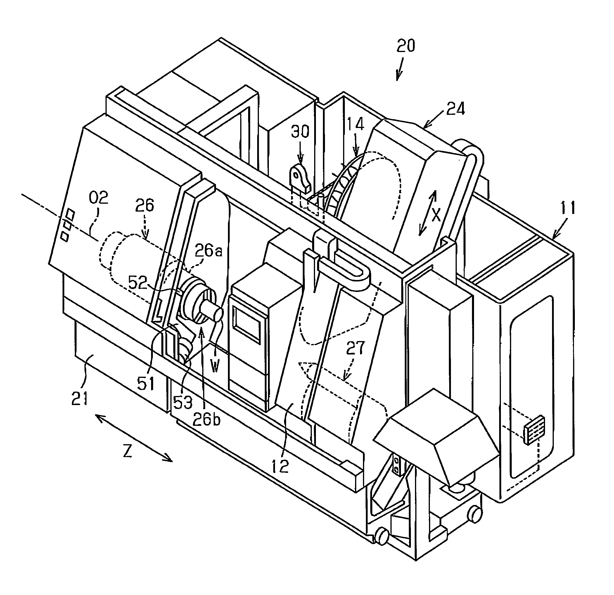
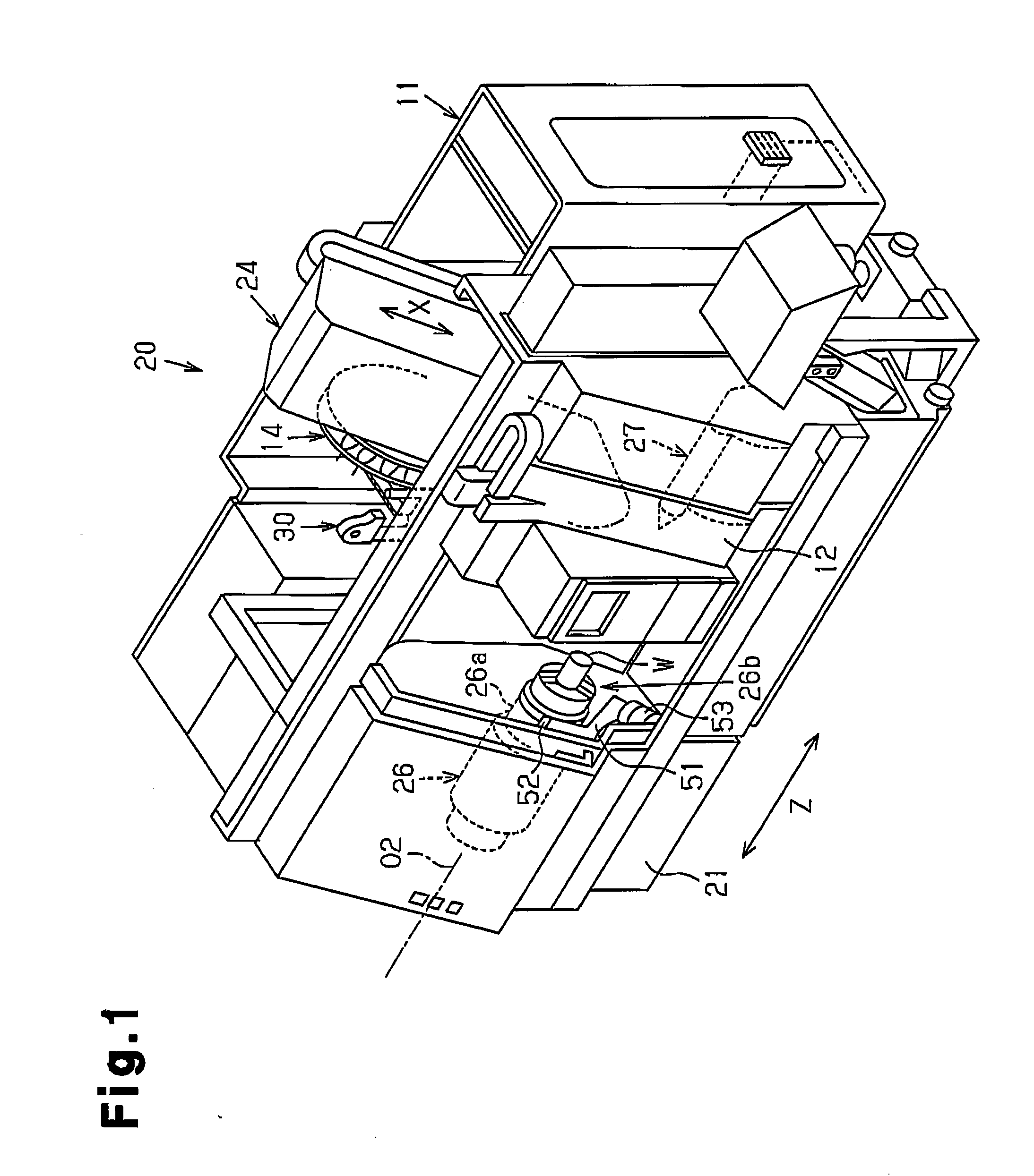
[0048]As shown in FIGS. 1 and 2, a CNC combined lathe apparatus (hereinafter referred to as combined lathe apparatus) 20 has a bed 21 and a frame 11 which are in rectangular parallelepiped form and extend in a Z axis. A front door 12 is provided on the front surface of the frame 11 so as to be openable and closeable. A headstock 26 is installed above the bed 21. A workpiece spindle 26a is supported by the headstock 26 so as to be rotatable around an axis O2. The workpiece spindle 26a is placed in such a manner that the axis O2 is parallel to the Z axis.

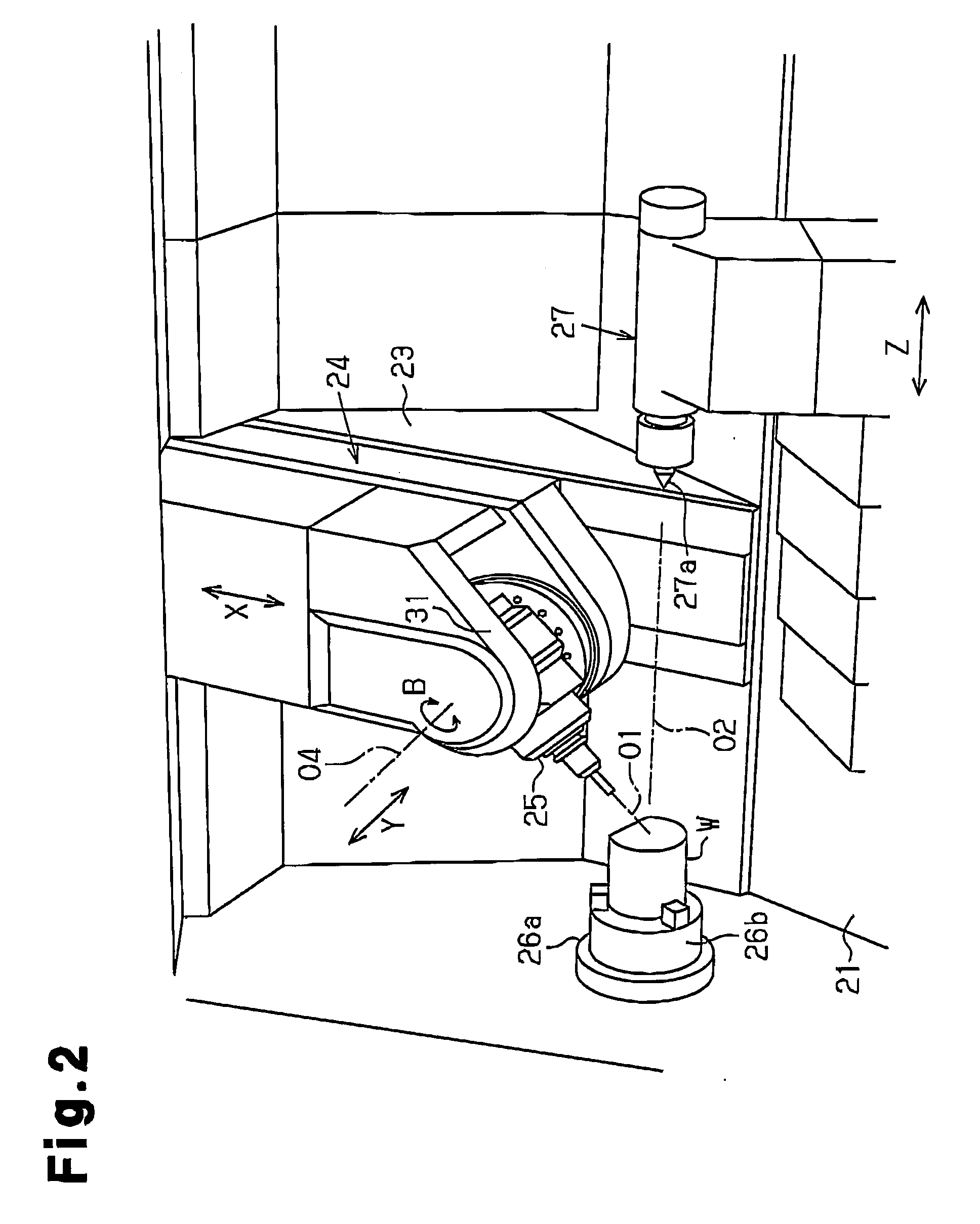
[0049]A chuck 26b is provided in the workpiece spindle 26a. A workpiece W to be processed is mounted on the chuck 26b. A tailstock 27 is placed above the bed 21 so as to face the headstock 26. The tailstock 27 is moveable along the Z axis. A tailstock barrel 27a ...

second embodiment

[0108]According to the prior art, a turning process is carried out on a workpiece W in the cutting location shown in FIG. 6(B) and in the X-Z plane. At this time, the blade of the turning process tool is located in the X-Z plane, which includes the center around which the workpiece W rotates, and along the axis O1 of the tool spindle 25. Positioning of the turning process tool in this location is referred to as core height adjustment. This core height adjustment is known to have an effect on the precision in processing and the quality of the processed surface. A turning tool is attached to the turning tool holder, and a turning tip is attached to the turning tool. The thickness Th of commercially available turning tools, to which a turning tip is attached, is usually standardized. The turning tool holder is designed taking the thickness Th of the turning tool into consideration so that the blade of the turning tool coincides with the axis O2 of the workpiece spindle 26a. That is to ...

third embodiment

[0136]Next, the blade position detecting apparatus 50 which is used in the above described combined lathe apparatus 20 is described with reference to FIGS. 1 and 8 to 10.

[0137]A support portion 53 is provided in the vicinity of the workpiece spindle 26a, above a bed 21. An arm 51 which extends along the Z axis is supported by the support portion 53 in such a manner as to be rotatable. A detection portion main body 52 which is used for a combined lathe apparatus 20 is provided at a distal end of the arm 51. The detection portion main body 52 is placed in the vicinity of the axis O2 of the workpiece spindle 26a. The support portion 53 is omitted in FIG. 8. The arm 51 is rotated by the support portion 53 when a turning process is carried out on the workpiece W, so that the detection portion main body 52 stands by outside the region where the main body is to be processed.

[0138]A main body case 54 is attached to the arm 51. A needle member 55 is supported within the main body case 54 in ...


PUM

PropertyMeasurementUnit
angleaaaaaaaaaa
angleaaaaaaaaaa
lengthaaaaaaaaaa

Abstract

A carriage is moved in a direction including a Y axis component in order to move a turning process tool that is attached to a tool spindle along a horizontal line that is perpendicular to a Z axis, and thus, a turning process is carried out on a workpiece which is attached to a workpiece spindle.

Description

BACKGROUND OF THE INVENTION[0001]The present invention relates to a method for controlling a combined lathe apparatus, a combined lathe apparatus, a turning tool holder, a blade position registering apparatus, and a blade position detecting apparatus.[0002]The basic design concepts for combined lathe apparatuses include the following 1) to 3).[0003]These are the most important points which should be taken into consideration at the time of design.[0004]1) The operator can come close to a workpiece and the tool headstock, which is easy to use.[0005]2) The space for installing the machine tool within a factory is small.[0006]3) Chips can be smoothly discharged and the chips are easy to be processed.[0007]Thus, as shown in FIGS. 12(A) to 12(C), apparatuses having a moveable body 420, which is inclined by a predetermined angle θ relative to the horizontal line, have been used as a combined lathe apparatus having an automatic tool replacing apparatus. In general, the predetermined angle θ...

Claims


Application Information

Patent Timeline
Patent Type & Authority Applications(United States)
IPC IPC(8): B23B3/00B23B3/34B23C7/00G01S3/802B26D5/00
CPCB23B1/00Y10T82/2506B23Q11/001B23B3/161B23B29/26Y10T82/2508Y10T82/2585Y10T82/2561Y10T29/5109Y10T483/1705Y10T409/309352Y10T82/2524Y10T82/10Y10T29/5114Y10T82/2587B23B3/06B23Q3/15513B23Q3/1572B23Q3/1578Y10T83/088B23B3/065B23Q3/15713
Inventor MOMOI, SHOJIOKUDA, TOSHIHITOYAMAMOTO, HIROMASA
Owner YAMAZAKI MAZAK KK
Why Eureka
Try Eureka