
Device and Method for Printing Labels

a label and device technology, applied in the field of pharmaceutical prescription dispensing, can solve the problems of low speed at which prescriptions are filled, and the absence of a closure (i.e., a lid) on the container after it is filled in these systems, and achieve the effect of simplifying the labeling process

Inactive Publication Date: 2008-11-20
PARATA SYST
View PDF16 Cites 18 Cited by
  • Summary
  • Abstract
  • Description
  • Claims
  • Application Information

AI Technical Summary

Benefits of technology

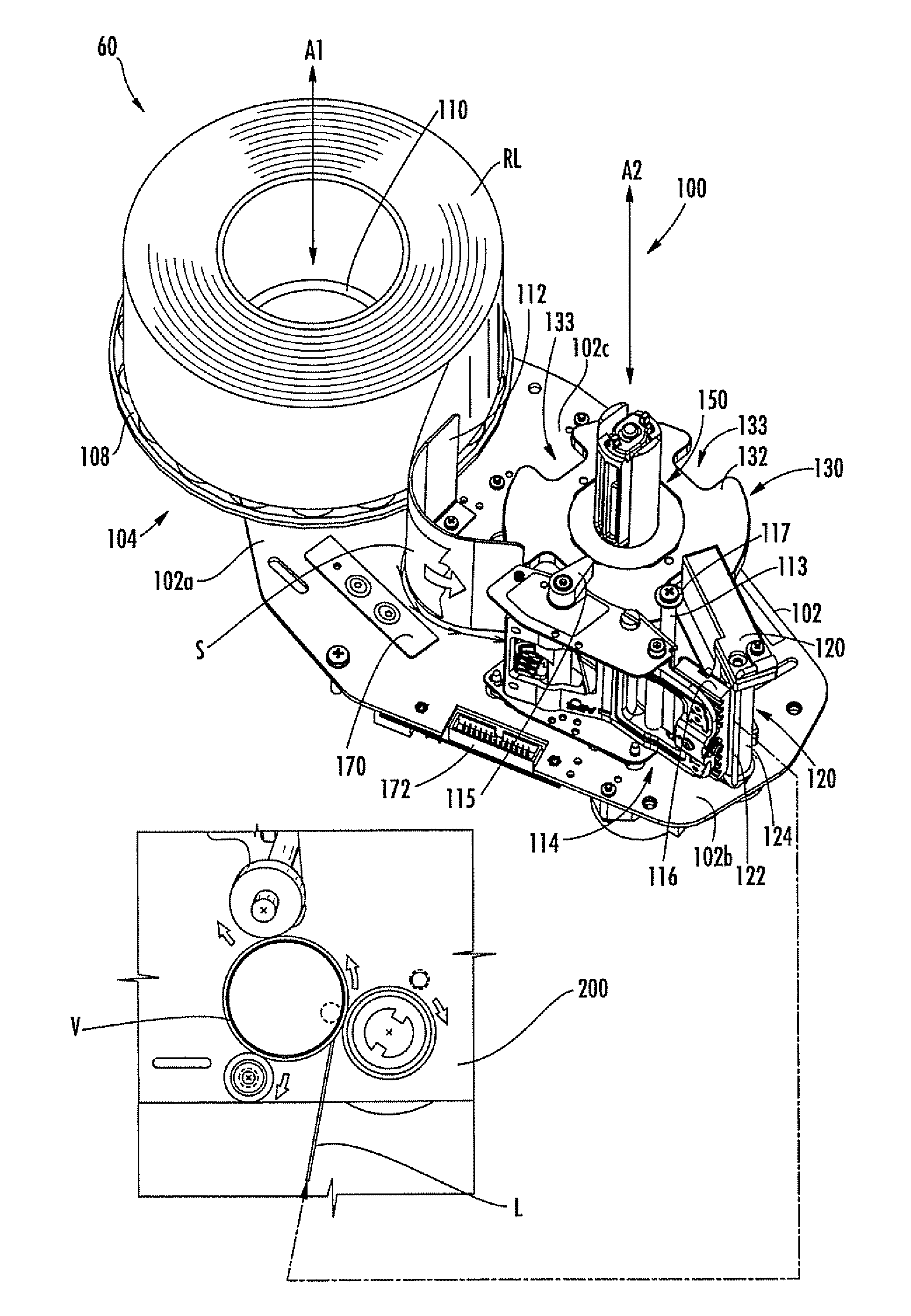
[0007]As a first aspect, embodiments of the present invention are directed to a label printing station for an object. The label printing station comprises: a base; a label supply wheel rotatably mounted to the base for rotation about a first vertical axis of rotation; a label backing take-up wheel rotatably mounted to the base for rotation about a second vertical axis of rotation; and a label print-head assembly mounted to the base, the label print-head assembly being configured to print on a label as the label is vertically oriented. The supply wheel, the print-head assembly and the take-up wheel serially define a paper path along which a substantially continuous label backing sheet travels. The label printing station further comprises a labeling station configured to apply a label to an object, the labeling station being positioned to receive a printed label from the print-head assembly and apply it to the object. With the printed label being vertically oriented, the label can be attached to a vertically oriented object, such as a pharmaceutical vial, which can simplify the labeling process.
[0008]As a second aspect, embodiments of the present invention are directed to a method of presenting a printed label for an object. The method comprises; conveying a label adhered to a substantially continuous label backing sheet past a print head assembly, the label and backing sheet being vertically oriented; printing pharmaceutical information on the label with the print head assembly as the label is vertically oriented; removing the vertically oriented printed label from the backing sheet for presentation to an object; and adhering the vertically oriented printed label to the object. Again, the vertical orientation of the label can facilitate the attachment to a vertically oriented object, such as a pharmaceutical vial.
[0009]As a third aspect, embodiments of the present invention are directed to a peel block for use with a label print-head assembly. The peel block comprises: a body section with opposed first and second side walls; at least one foot having an upper surface that defines a lower edge of a paper path followed by a backing sheet with labels adhered thereto, the foot extending from the first side wall; and at least one foot having an upper surface that defines a lower edge of the paper path, the foot extending from the second side wall. A peel block of this configuration can help to maintain a vertically-oriented label backing sheet in vertical alignment.
[0010]As a fourth aspect, embodiments of the present invention are directed to a method of presenting a printed label for an object, comprising: conveying a label adhered to a substantially continuous label backing sheet past a print head assembly, the label and backing sheet being vertically oriented; printing information on the label with the print head assembly as the label is vertically oriented; and removing the vertically oriented printed label from the backing sheet for presentation to an object. During the conveying step, the backing sheet is supported from underneath at multiple locations. This technique can facilitate proper application of a vertically oriented printed label to the object.

Problems solved by technology

Drawbacks to these systems typically include the relatively low speed at which prescriptions are filled and the absence in these systems of securing a closure (i.e., a lid) on the container after it is filled.

Method used


Image

  • Device and Method for Printing Labels
  • Device and Method for Printing Labels
  • Device and Method for Printing Labels

Examples


Embodiment Construction

[0029]The present invention will now be described more fully hereinafter, in which preferred embodiments of the invention are shown. This invention may, however, be embodied in different forms and should not be construed as limited to the embodiments set forth herein. Rather, these embodiments are provided so that this disclosure will be thorough and complete, and will fully convey the scope of the invention to those skilled in the art. In the drawings, like numbers refer to like elements throughout. Thicknesses and dimensions of some components may be exaggerated for clarity.

[0030]Unless otherwise defined, all terms (including technical and scientific terms) used herein have the same meaning as commonly understood by one of ordinary skill in the art to which this invention belongs. It will be further understood that terms, such as those defined in commonly used dictionaries, should be interpreted as having a meaning that is consistent with their meaning in the context of the releva...


PUM

PropertyMeasurementUnit
speedaaaaaaaaaa
sizeaaaaaaaaaa
axis of rotationaaaaaaaaaa

Abstract

A label printing station includes: a base; a label supply wheel rotatably mounted to the base for rotation about a first vertical axis of rotation; a label backing take-up wheel rotatably mounted to the base for rotation about a second vertical axis of rotation; and a label print-head assembly mounted to the base, the label print-head assembly being configured to print on a label as the label is vertically oriented. The supply wheel, the print-head assembly and the take-up wheel serially define a paper path along which a substantially continuous label backing sheet travels. The backing sheet may be supported from underneath at multiple locations along the paper path. With the printed label being vertically oriented, the label can be attached to an object, such as a vertically oriented pharmaceutical vial, which can simplify the labeling process.

Description

RELATED APPLICATION[0001]This application claims priority from U.S. Provisional Patent Application No. 60 / 938,869, filed May 18, 2007 and entitled Device and Method for Printing Labels, the disclosure of which is hereby incorporated herein in its entirety.FIELD OF THE INVENTION[0002]The present invention is directed generally to the dispensing of prescriptions of pharmaceuticals, and more specifically is directed to the automated dispensing of pharmaceuticals.BACKGROUND OF THE INVENTION[0003]Pharmacy Generally began with the compounding of medicines, which entailed the actual mixing and preparing of medications. Heretofore, pharmacy has been, to a great extent, a profession of dispensing, that is, the pouring, counting, and labeling of a prescription, and subsequently transferring the dispensed medication to the patient. Because of the repetitiveness of many of the pharmacist's tasks, automation of these tasks has been desirable.[0004]Some attempts have been made to automate the pha...

Claims


Application Information

Patent Timeline
Patent Type & Authority Applications(United States)
IPC IPC(8): B32B38/14
CPCB65C9/0006Y10T156/1956B65C9/1869
Inventor SINK, JOHN RICHARD
Owner PARATA SYST
Learn More