Multilayer ceramic substrate

a multi-layer ceramic and substrate technology, applied in the direction of electrical apparatus construction details, transportation and packaging, electrical components association, etc., can solve the problems of not always obtaining satisfactory dimensional accuracy or satisfactory flatness, failing to mount electronic devices on the bottom, and reducing the dimensional accuracy of multi-layer ceramic substrates. , to achieve the effect of sufficiently secure cavity bottom flatness and secured dimensional accuracy

Inactive Publication Date: 2008-11-20
TDK CORPARATION
View PDF5 Cites 3 Cited by
  • Summary
  • Abstract
  • Description
  • Claims
  • Application Information

AI Technical Summary

Benefits of technology

[0011]To attain the above object, the present invention provides a multilayer ceramic substrate having a cavity and a production method thereof. The production method comprises the steps of laminating a plurality of substrate green sheets including cavity formation green sheets having through holes corresponding to the cavity to form a multilayer body, pressing the multilayer body and firing the pressed body, the method further comprising the steps of, before the pressing step, laminating shrinkage suppression green sheet pieces on surfaces of the substrate green sheets, respectively, which surfaces constitute an outermost layer of the multilayer body, laminating a shrinkage suppression green sheet piece on a substrate green sheet constituting a bottom of the cavity, disposing on the shrinkage suppression green sheet piece an embedded green sheet separate from the cavity formation green sheets to fill in the cavity and, after the firing step, removing the embedded green sheet fired. In the above production method, since the non-shrinkage firing process is performed, with the shrinkage suppression green sheet disposed also on the substrate green sheets exposed to the bottom of the cavity, as described above, the dimensional accuracy is secured and, also, the flatness of the cavity bottom is sufficiently secured. At the same time, the pressing step of the multilayer body is performed, with the embedded green sheet disposed in the cavity, the pressing step is easy to perform with a flat mold die in the same manner as in the case of pressing a multilayer body having no cavity, and there is no possibility of deformation including cavity opening collapse and bulge of the periphery of the cavity opening.

Problems solved by technology

This is a serious cause in decreasing the dimensional accuracy of the multilayer ceramic substrate.
When fabricating a multilayer ceramic substrate having the cavity mentioned above, even an application of the non-shrinkage firing process poses a problem of not always obtaining satisfactory dimensional accuracy or satisfactory flatness.
When the binding force of shrinkage suppression is not exerted onto the bottom of the cavity, flatness of the bottom required for mounting an electronic device thereon cannot be secured to the effect that there is a possibility of failing to mount the electronic device on the bottom.
However, only disposition of the shrinkage-suppressing sheet on the ceramic green sheet for the substrate that will constitute the bottom of the cavity is difficult to completely eliminate the problem of the deformation etc. of the cavity.
Particularly, the method for producing a multilayer ceramic substrate requires a step of pressing a multilayer body having a plurality of green sheets laminated and, in the pressing step of the method for producing a multilayer ceramic substrate having a cavity, there is a fair possibility of the cavity opening being collapsed and deformed in the pressing step.
Also in the firing step, a phenomenon of rendering the periphery of the cavity opening to bulge will occur, thus raising a possibility of the cavity opening being deformed.
However, since the sintered multilayer body is hard and fragile, a process with high accuracy is difficult to perform and expensive equipment is required to use, leading to a high production cost.

Method used


Image

  • Multilayer ceramic substrate
  • Multilayer ceramic substrate
  • Multilayer ceramic substrate

Examples


example 1

[0366]In this example, an alumina-glass-based dielectric material was prepared as a material for a ceramic green sheet. A binder and organic solvent were mixed with the material to obtain a mixture, and the mixture was subjected to the doctor blade method to produce a ceramic green sheet having a thickness of 125 μm. On the other hand, a tridymite-silica-based material was prepared as a material for shrinkage suppression. Similarly to the ceramic green sheet material, a binder and organic solvent were mixed with the material to obtain a mixture, and the mixture was subjected to the doctor blade method to produce a shrinkage suppression green sheet having a thickness of 125 μm.

[0367]The ceramic green sheet was formed with a first square through hole having a side of 4 mm using a die. On the other hand, the shrinkage suppression green sheet was similarly punched out using a die to form a first fitting sheet of a square having a side of 4 mm. The first fitting sheet was fitted in the f...

example 2

[0371]In this example, a multilayer ceramic substrate having a multistage cavity was fabricated. The production method set forth in the second embodiment was used herein. The ceramic green sheet and shrinkage green sheet were formed pursuant to Example 1.

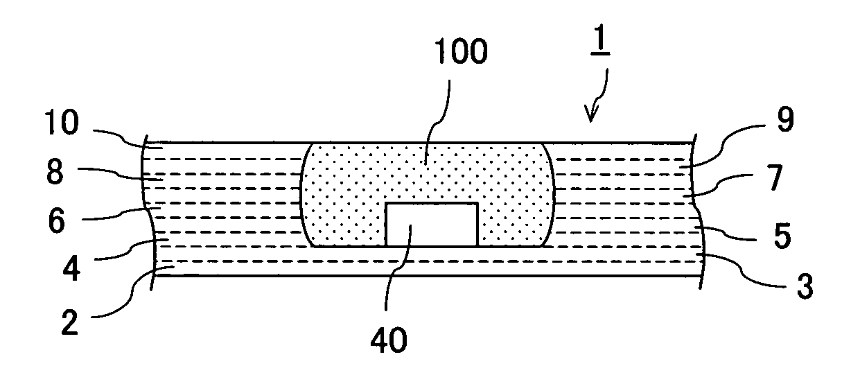
[0372]In the multilayer ceramic substrate, the first cavity portion had a side of 5 mm at the opening and a depth of 0.24 mm, and the second cavity portion had a side of 2 mm at the opening and a depth of 0.18 mm. A photograph showing the cross section of the multilayer is shown in FIG. 74 from which it is found that each of the cavity portions has a shape of a drum having a larger opening area at the inside than at the opening.

example 3

[0373]In this example, an alumina-glass-based dielectric material was prepared as a ceramic material for a substrate and mixed with an organic binder and organic solvent to obtain a mixture. The mixture was subjected to the doctor blade method to produce a ceramic green sheet having a thickness of 125 μm

[0374]On the other hand, a tridymite-silica-based material was prepared as a material for shrinkage suppression and mixed with an organic binder and organic solvent similarly to the ceramic material to obtain a mixture. The mixture was subjected to the doctor blade method to produce shrinkage suppression green sheets having a thickness of 110 μm and a thickness of 125 μm, respectively. As a burnable material, the aforementioned ceramic material for the substrate and the resin used when the shrinkage suppression material was formed into a sheet were prepared. The burnable material was dissolved in an organic solvent and the resultant was subjected to the doctor blade method to produce...


PUM

PropertyMeasurementUnit
distanceaaaaaaaaaa
distanceaaaaaaaaaa
shrinkageaaaaaaaaaa

Abstract

A multilayer ceramic substrate includes a plurality of ceramic layers laminated each other. The plurality of ceramic layers form a bulge and a cavity having such a shape that an opening area of the cavity gradually becomes smaller toward a bottom of the cavity.

Description

CROSS REFERENCE TO RELATED APPLICATION[0001]This is a divisional application of patent application Ser. No. 11 / 405,462 filed on Apr. 18, 2006.BACKGROUND OF THE INVENTION AND RELATED ART STATEMENT[0002]The present invention relates to a multilayer ceramic substrate having a cavity, particularly to an improvement regarding a multilayer ceramic substrate having a cavity utilizing a non-shrinkage firing process and a multilayer ceramic substrate having a cavity of a specific shape. In the fields of electronics or other such devices, substrates for mounting electronic devices thereon have been being widely used. In recent years, however, multilayer ceramic substrates have been proposed and put to practical use as substrates satisfying demands for reduction in size and weight and for multifunctionality and having high reliability. A multilayer ceramic substrate is constituted by a plurality of ceramic layers laminated, and integral incorporation of a wiring conductor or an electronic devi...

Claims


Application Information

Patent Timeline
Patent Type & Authority Applications(United States)
IPC IPC(8): H05K1/18
CPCH01L21/4807Y10T29/49126H01L23/13H01L23/15H01L2224/48091H01L2224/48227H01L2924/01012H01L2924/01025H01L2924/01046H01L2924/09701H01L2924/15153H01L2924/15157H01L2924/1517H01L2924/15787H05K1/0306H05K1/183H05K3/4629H05K3/4697H05K2203/063H05K2203/308H01L21/4857Y10T156/1056H01L24/48H01L2924/01019H01L2924/01322Y10T29/49163Y10T29/49155Y10T428/24926H01L2924/00014H01L2924/12042H01L2924/15156H01L2924/00H01L2224/45099H01L2224/45015H01L2924/207H05K3/46
Inventor ENDOU, KENJIHATANAKA, KIYOSHIHIRAKAWA, MASAHARUNISHINO, HARUOFUJIOKA, HIDEAKI
Owner TDK CORPARATION
Why Eureka
Try Eureka