

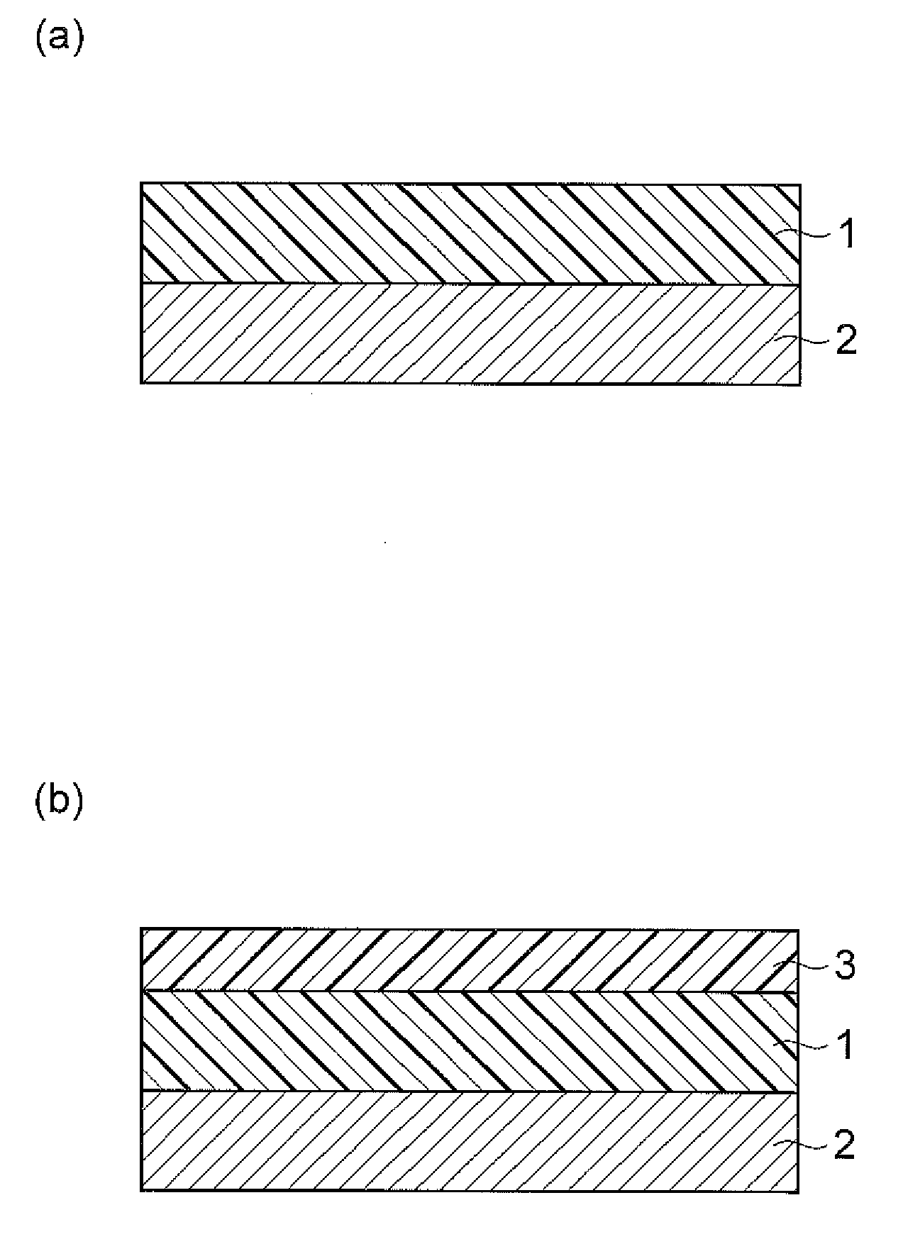
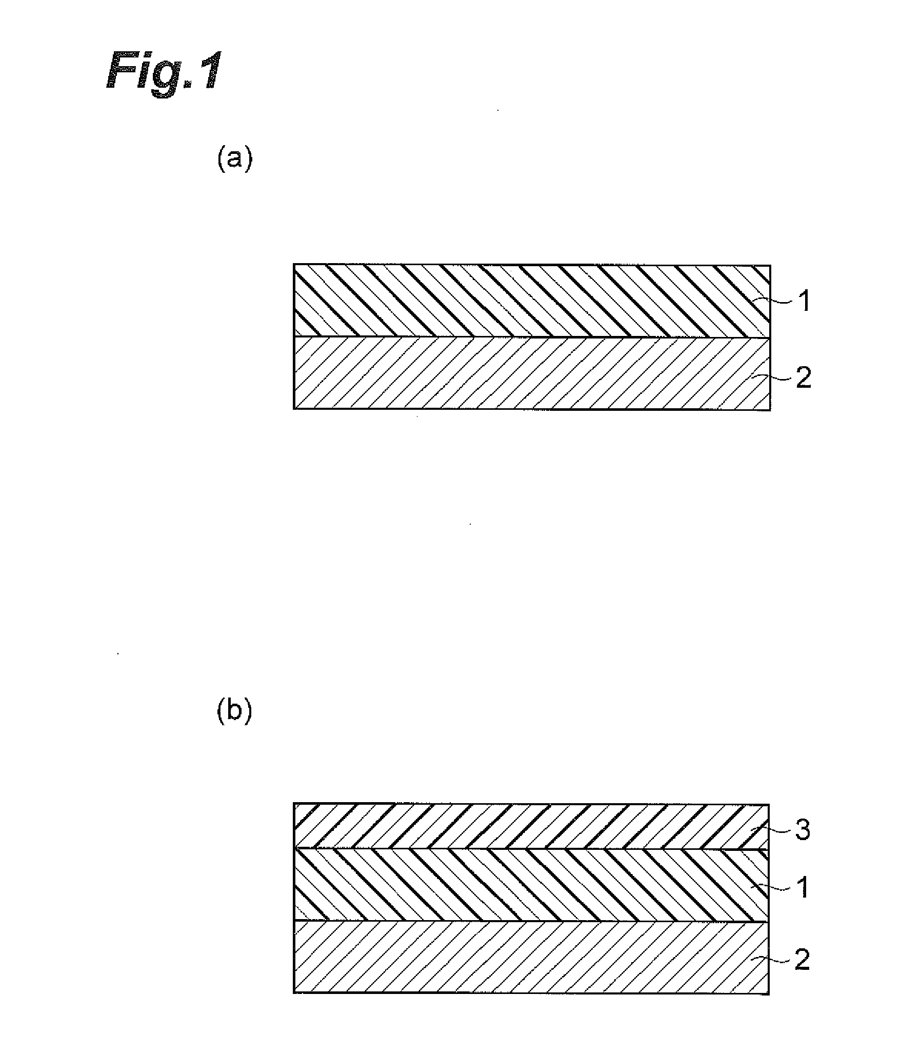
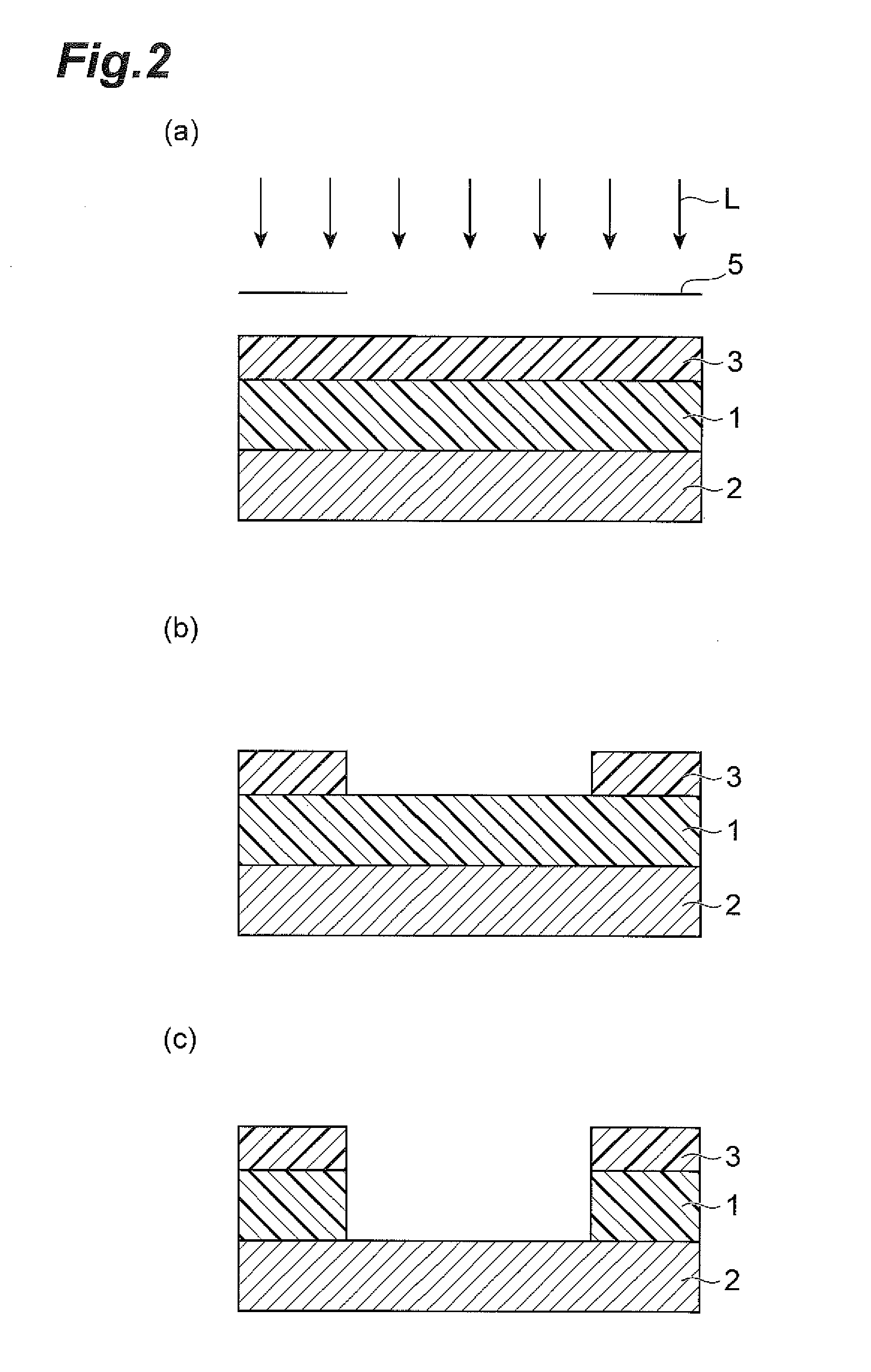
Method for manufacturing adhesion body, method for manufacturing substrate with adhesive pattern, and substrate with adhesive pattern
a manufacturing method and adhesive technology, applied in the direction of film/foil adhesives, heat-activated film/foil adhesives, instruments, etc., can solve the problems of insufficient adhesion strength, low continuous workability, and difficulty in keeping flatness to ends, so as to suppress the occurrence of voids, sufficient adhesion strength, and sufficient flatness
- Summary
- Abstract
- Description
- Claims
- Application Information
AI Technical Summary
Benefits of technology
Problems solved by technology
Method used
Image

Examples
synthesis example 1
[0109]32.8 g (0.08 moles) of 2,2-bis(4-aminophenoxyphenyl)propane (hereinafter abbreviated as “BAPP”), 4.09 g (0.02 moles) of aliphatic polyether diamine (“B-12” manufactured by BASF, hereinafter abbreviated as “B-12”), and 100 g of dimethylacetamide were placed in a 500 ml four-neck flask equipped with a thermometer, a stirrer, and a calcium chloride tube, and stirred. After the dissolution of diamine, 51.4 g (0.10 moles) of decamethylenebistrimellitate dianhydride (hereinafter abbreviated as “DBTA”) was added in small amounts, while the flask was cooled in an ice bath. After the completion of the addition, a reaction was performed in the ice bath for 3 hours, and further at room temperature for 4 hours, and then, 25.5 g (0.25 moles) of acetic anhydride and 19.8 g (0.25 moles) of pyridine were added and stirred at room temperature for 2 hours. The reaction liquid was poured into water, and a precipitate was collected by filtration and dried to obtain a thermoplastic resin A having ...
synthesis example 2
[0110]41 g (0.1 moles) of BAPP and 150 g of dimethylacetamide were placed in a 500 ml four-neck flask equipped with a thermometer, a stirrer, and a calcium chloride tube, and stirred. After the dissolution of diamine, 41 g (0.1 moles) of ethylenebistrimellitate dianhydride was added in small amounts, while the flask was cooled in an ice bath. After a reaction was performed at room temperature for 3 hours, 30 g of xylene was added, and heating was performed at 150° C., while an N2 gas was blown in, to azeotropically remove the xylene with water. The reaction liquid was poured into water, and a precipitate was collected by filtration and dried to obtain a thermoplastic resin B having an imide skeleton.
synthesis example 3
[0111]32.8 g (0.08 moles) of BAPP, 3.97 g (0.02 moles) of B-12, and 100 g of dimethylacetamide were placed in a 500 ml four-neck flask equipped with a thermometer, a stirrer, and a calcium chloride tube, and stirred. After the dissolution of diamine, 10.4 g (0.02 moles) of decamethylenebistrimellitate dianhydride and 24.8 g (0.08 moles) of 4,4′-oxydiphthalic dianhydride (hereinafter abbreviated as “ODPA”) were added in small amounts, while the flask was cooled in an ice bath. After the completion of the addition, a reaction was performed in the ice bath for 3 hours, and further at room temperature for 4 hours, and then, 25.5 g (0.25 moles) of acetic anhydride and 19.8 g (0.25 moles) of pyridine were added and stirred at room temperature for 2 hours. The reaction liquid was poured into water, and a precipitate was collected by filtration and dried to obtain a thermoplastic resin C having an imide skeleton.
PUM
| Property | Measurement | Unit |
|---|---|---|
| temperature | aaaaa | aaaaa |
| temperature | aaaaa | aaaaa |
| temperature | aaaaa | aaaaa |
Abstract
Description
Claims
Application Information