Two-level mounting board and crystal oscillator using the same

a mounting board and crystal oscillator technology, applied in the direction of fixed connections, manufacturing tools, soldering apparatus, etc., can solve the problems of deteriorating joint strength of metal pins b>4/b>, inability to use configuration in practice, and inability to accurately implant metal pins b>4/b>, etc., to achieve reliable connection

Inactive Publication Date: 2008-11-20
NIHON DEMPA KOGYO CO LTD
View PDF6 Cites 2 Cited by
  • Summary
  • Abstract
  • Description
  • Claims
  • Application Information

AI Technical Summary

Benefits of technology

[0014]Since this configuration ensures that part of the electrode land is cut away to open it, a connective portion is formed between the hole and the outer atmosphere, without solder adhering within that cutaway portion. Consequently, if any air expands within the hole due to heat generated during the soldering of the component or by solder reflow when the component is mounted on a set substrate, that air is vented from the connective portion into the outer atmosphere. This enables a reliable connection of each metal pin onto the first substrate, with no breaks in the connective soldering.
[0015]The present invention also states that the second substrate is positioned on a stopper that protrudes as a disk provided at the upper end of the metal pin. This ensures that the second substrate is positioned reliably on the metal pin, ensuring a horizontal orientation with respect to the first substrate.
[0016]The present invention also relates to a crystal oscillator in which a crystal vibrator housed in a constant-temperature oven is provided on a lower surface of the second substrate, and also a circuit element is disposed on an upper surface of the second substrate. This makes it possible to provide a constant-temperature oscillator in which the operating temperature of the crystal vibrator is constant.

Problems solved by technology

This causes problems in that the metal pins 4 cannot be implanted accurately with respect to the first substrate 1a and the joint strength of the metal pins 4 deteriorates.
However, this configuration cannot be used in practice because, if a circuit pattern is formed on the set substrate on which the constant-temperature oscillator is mounted, there would be a danger of electrical contact between the metal pins 4 in the holes 5 and that circuit pattern.

Method used


Image

  • Two-level mounting board and crystal oscillator using the same
  • Two-level mounting board and crystal oscillator using the same
  • Two-level mounting board and crystal oscillator using the same

Examples


Embodiment Construction

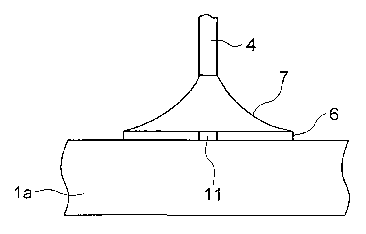
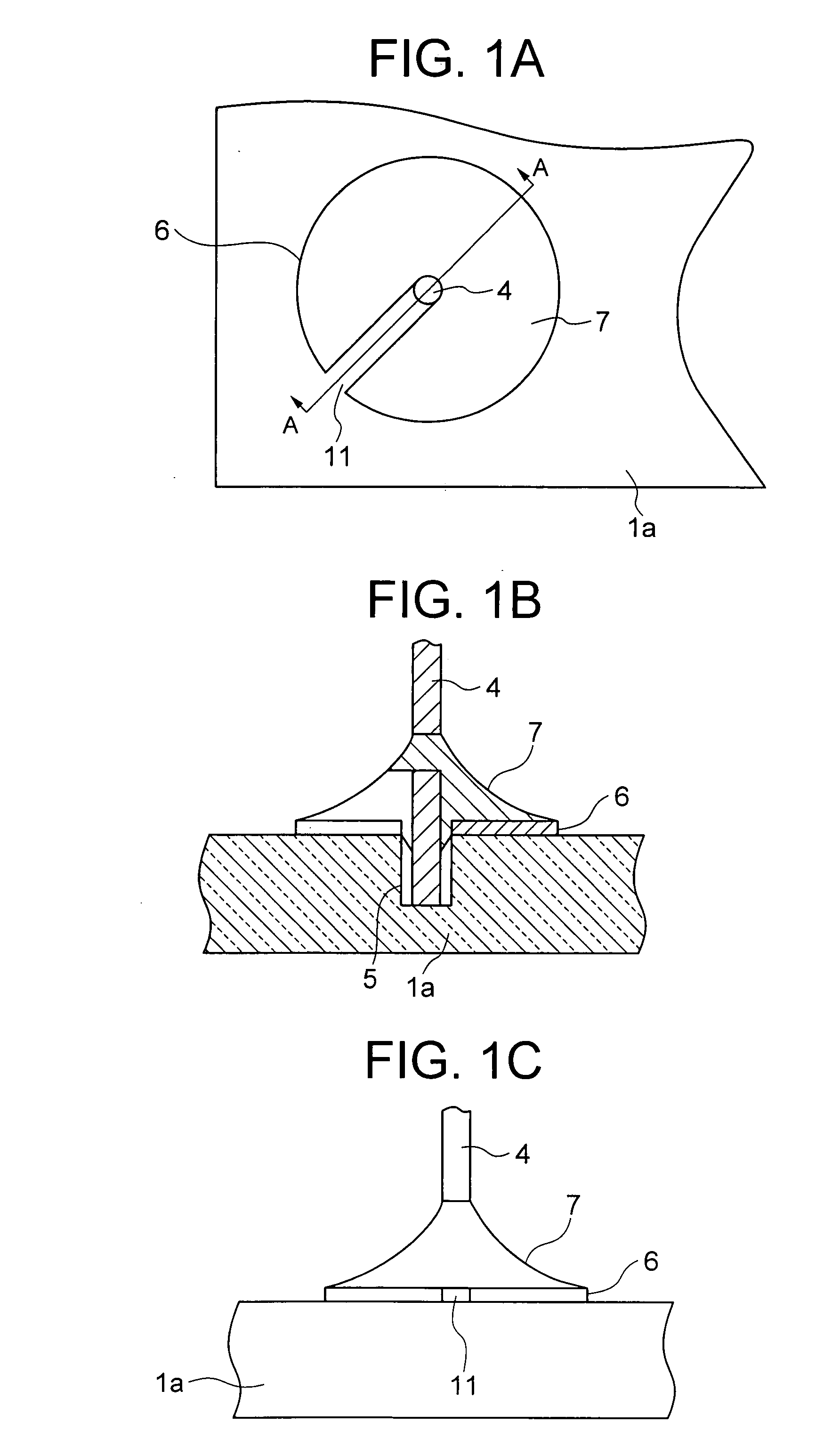
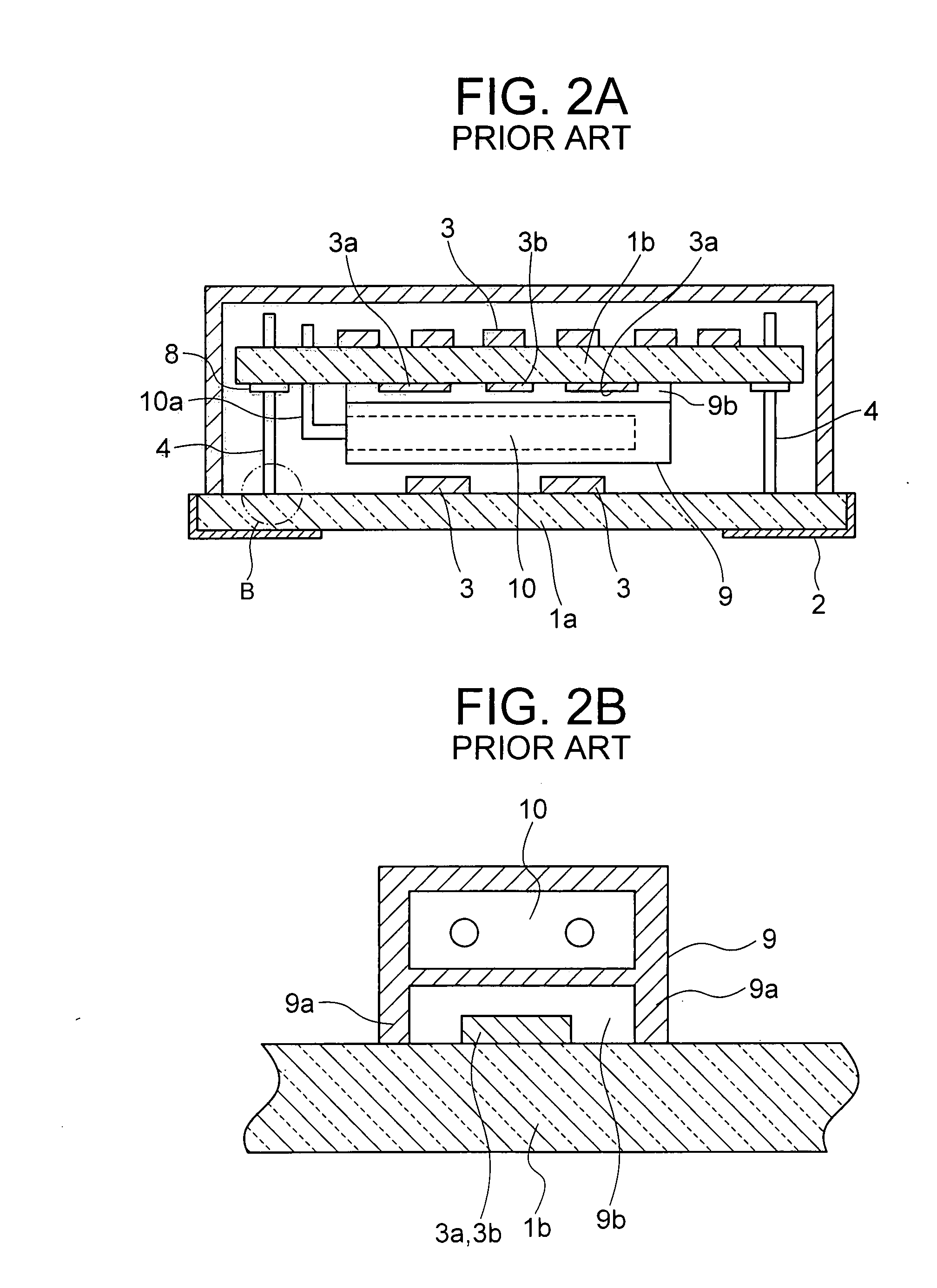
[0020]An embodiment of a two-level mounting board for a constant-temperature oscillator in accordance with the present invention is shown in FIG. 1, where FIG. 1A is a partial enlarged plan view of a portion of a first substrate at which a metal pin is erected, FIG. 1B is a partial enlarged section along the line A-A of FIG. 1A through the portion at which the metal pin is erected in the first substrate, and FIG. 1C is a side view as seen from an opened portion (cutaway portion) of the electrode land. Note that portions that are the same as those of the prior-art example are denoted by the same reference numbers, and further description thereof is either abbreviated or omitted.

[0021]The constant-temperature oscillator in accordance with the present invention is configured of a two-level mounting board in which the second substrate 1b is supported horizontally above the first substrate 1a by a plurality of the metal pins 4. In this case, the first substrate 1a is a stacked substrate ...


PUM

PropertyMeasurementUnit
temperatureaaaaaaaaaa
resonant frequencyaaaaaaaaaa
constant-temperatureaaaaaaaaaa

Abstract

The present invention relates to a two-level mounting board in which a second substrate is supported horizontally by a metal pin above a first substrate having a mounting electrode on an outer base surface, the free, lower end of the metal pin is inserted in a hole provided in the surface of the first substrate, and the metal pin is affixed by solder to an annular electrode land provided on the surface of the first substrate to form an outer periphery of the hole, wherein part of the ring of the annular electrode land is cut away to open the same. This provides a two-level mounting board in which metal pins can be connected reliably to the first substrate to support the second substrate horizontally, and a crystal oscillator using the same.

Description

FIELD OF THE INVENTION[0001]The present invention relates to a two-level mounting board in which one mounting board is supported by using metal pins, together with a crystal oscillator using the same, and, in particular, to a structure by which a metal pin is erected therein.BACKGROUND OF THE INVENTION[0002]Crystal oscillators are widely used in communications equipment or the like, as frequency reference sources. One type is a constant-temperature type of crystal oscillator (hereinafter abbreviated to “constant-temperature oscillator”) for installation into communications equipment such as ground stations or relay stations, in which a crystal vibrator is housed within a constant-temperature oven to keep the operating temperature thereof constant, whereby the resonant frequency thereof is maintained to be highly stable.DESCRIPTION OF RELATED ART[0003]A prior-art of a constant-temperature oscillator is shown in FIGS. 2 and 3, where FIG. 2A is a longitudinal section through the consta...

Claims


Application Information

Patent Timeline
Patent Type & Authority Applications(United States)
IPC IPC(8): H03B5/30B32B3/24
CPCH01R43/0256H05K1/141H05K3/3447H05K3/368H05K2201/09036Y10T428/24612H05K2201/10303H05K2201/1084H05K2201/10871H05K2203/1178H01R12/52H05K2201/09463
Inventor UCHIDA, TAKESHIITO, MANABUKURODA, TOMOTAKA
Owner NIHON DEMPA KOGYO CO LTD
Why Eureka
Try Eureka