Liquid crystal display device

a liquid crystal display and display device technology, applied in the direction of lighting and heating apparatus, planar/plate-like light guides, instruments, etc., can solve the problems of obstructing the desire to thin the liquid crystal display device, lowering the cooling efficiency, and difficult to secure the air flow path for cooling the inner portion of the casing constructing the outer shape of the liquid crystal devi

Inactive Publication Date: 2008-11-20
MAXELL HLDG LTD
View PDF4 Cites 101 Cited by
  • Summary
  • Abstract
  • Description
  • Claims
  • Application Information

AI Technical Summary

Benefits of technology

[0027]In accordance with the present invention, there can be provided with the liquid crystal display device having the cooling mechanism in which the natural convection in the inner portion of the casing is not prevented by the blower device.

Problems solved by technology

If the liquid crystal display device is made thinner, it becomes hard to secure an air flow path for cooling an inner portion of a casing constructing an outer shape of the liquid crystal device.
Accordingly, there generated a problem that a cooling efficiency is lowered.
However, in the technique disclosed in the patent document 1, it is necessary to set a rotating space for rotating the transverse flow fan around a shaft provided in a lateral direction of the liquid crystal display device, and a space for arranging a rotating mechanism rotating the transverse flow fan, and there is generated an obstructing factor against the desire for making the liquid crystal display device thin.
This structure is structured such as to cool the inner portion of the casing by using both a forced convection generated by the blower device and a natural convection generated in the inner portion of the casing, however, if the blower device is installed near the lower end of the liquid crystal display device, the natural convection is disturbed by the flow of the forced convection generated by the blower device, and there is a problem that a whole of the inner portion of the casing of the liquid crystal display device can not be efficiently cooled.

Method used


Image

  • Liquid crystal display device
  • Liquid crystal display device
  • Liquid crystal display device

Examples


Embodiment Construction

[0045]A description will be in detail given below of a best mode for carrying out the present invention approximately using the accompanying drawings.

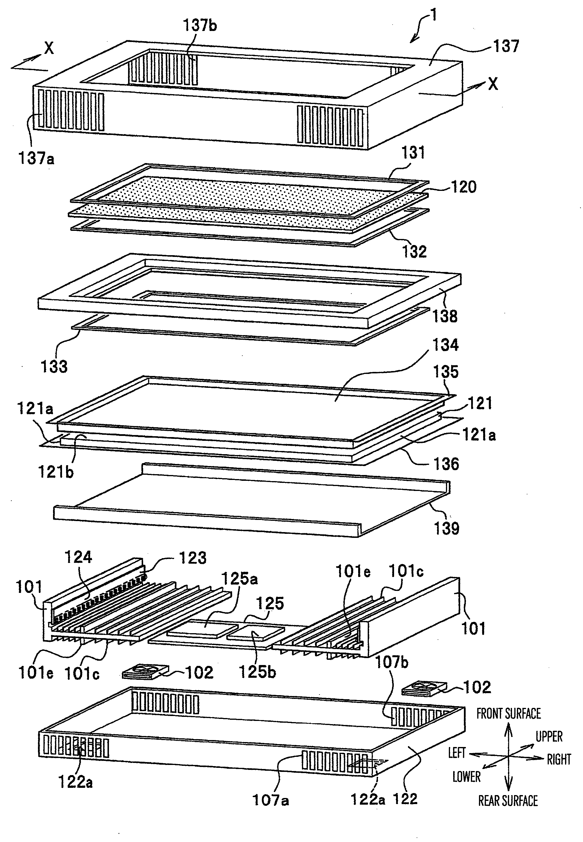
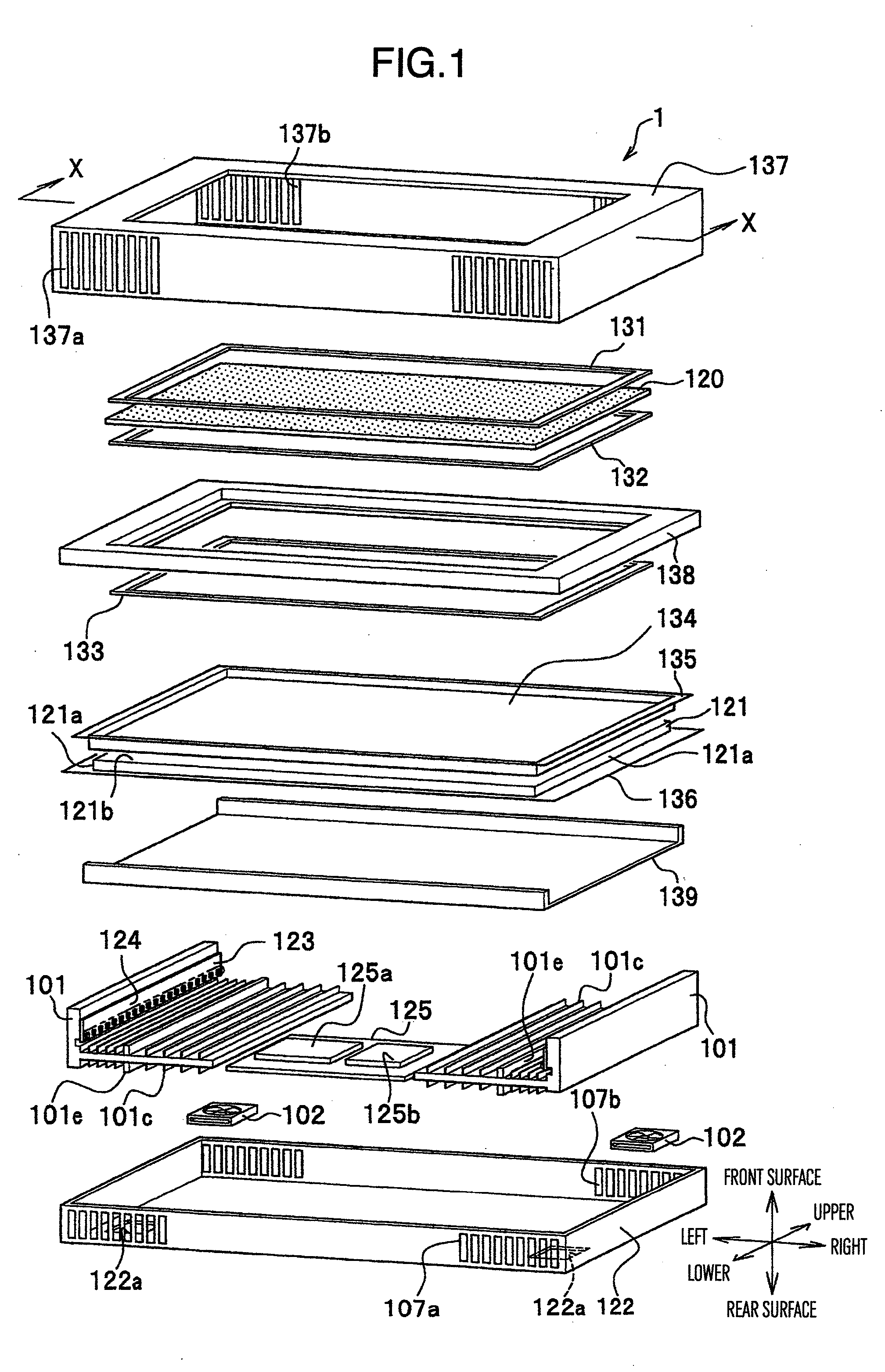
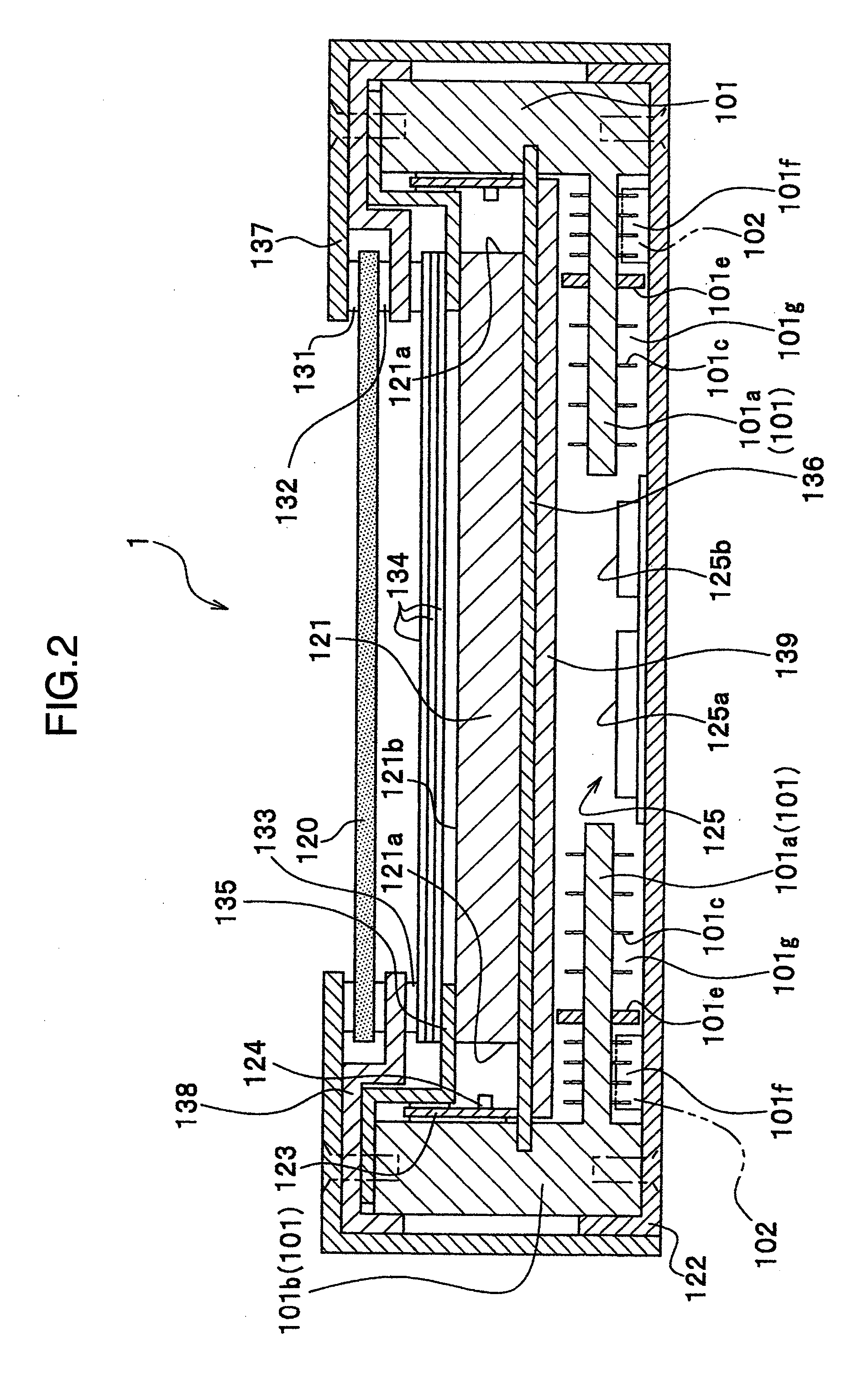
[0046]FIG. 1 is a perspective view of a structure of a liquid crystal display device in accordance with the present embodiment, FIG. 2 is a cross sectional view along a line X-X in FIG. 1, FIG. 3A is a view showing a wiring of a liquid crystal panel and a layout of a drive circuit, FIG. 3B is a view showing a layout of a thin film transistor (TFT) and a pixel electrode, FIG. 4A is a view showing a layout of a light source and a light guide plate, FIG. 4B is a view showing the light source, and FIG. 5 is a view showing an air supply and exhaust of the liquid crystal display device. In the present embodiment, as shown in FIG. 1, upper, lower, left, right, front and rear surfaces are defined on the basis of a display screen of a liquid crystal panel 120.

[0047]As shown in FIG. 1, a liquid crystal display device 1 in accordance with the pre...


PUM


Abstract

If a forced convection is generated by a cooling fan, there is generated a problem that a natural convection is prevented and a cooling effect in a region of the natural convection is lowered. The invention provides a structure in which an air flow generated by a forced convection does not come into contact with an air flow generated by a natural convection, by setting a partition all between a forced convection path in which the air flows on the basis of a forced convection generated by a cooling fan, and a natural convection path in which the air flows on the basis of a natural convection. Further, the partition wall is not provided near an upper end so as to draw in the air flowing through the natural convection path to a side of the forced convection path, thereby promoting the natural convection of the natural convection path.

Description

BACKGROUND OF THE INVENTION[0001](1) Field of the Invention[0002]The present invention relates to a liquid crystal display device having a cooling mechanism.[0003](2) Description of Related Art[0004]In recent years, as a display device, a luminous type plasma display panel or a non-luminous type liquid crystal display device have been frequently used in place of a cathode ray tube (CRT).[0005]Among them, the liquid crystal display device employs a liquid crystal panel as a transmission type light modulation element, and is provided with a lighting device (also called as a back light) on a back surface of the liquid crystal panel so as to irradiate a light onto the liquid crystal panel. Further, the liquid crystal panel forms an image by controlling a transmission rate of the light irradiated from the back light.[0006]One of the features of the liquid crystal display device exists in a point that an outer shape can be structured thinner than the CRT. However, a further thinner liquid...

Claims


Application Information

Patent Timeline
Patent Type & Authority Applications(United States)
IPC IPC(8): F21V29/00
CPCG02B6/003G02B6/0085G02B6/0086G02F1/133308G02F1/133385G02F2001/133628G02F2201/36H05K7/20972G02F1/133628
Inventor OHASHI, SHIGEONISHIJIMA, NORIYOSASAKI, SHIGEYUKI
Owner MAXELL HLDG LTD
Why Eureka
Try Eureka