
Power Output Apparatus, Control Method of Power Output Apparatus, and Vehicle Equipped with Power Output Apparatus

Active Publication Date: 2008-11-27
TOYOTA JIDOSHA KK
View PDF5 Cites 10 Cited by
  • Summary
  • Abstract
  • Description
  • Claims
  • Application Information

AI Technical Summary

Benefits of technology

[0004]The power output apparatus of the invention, the motor vehicle equipped with the power output apparatus, and the control method of the power output apparatus thus aim to quickly respond to an abrupt change of a driving force demand. The power output apparatus of the invention, the motor vehicle equipped with the power output apparatus, and the control method of the power output apparatus also aim to prepare for an abrupt change of a driving force demand according to the state of an accumulator unit, such as a secondary battery.
[0016]In still another preferable embodiment of the invention, the maximum / minimum control rotation speeds setting module sets the maximum control rotation speed to decrease with a decrease in absolute value of the set input limit of the accumulator unit. The power output apparatus sets the maximum control rotation speed to decrease with a decrease in absolute value of the set input limit of the accumulator unit. This increases a rotation speed difference between the maximum control rotation speed and the performance-based maximum rotation speed and thus provides a greater margin for an abrupt increase in rotation speed of the internal combustion engine driven at the maximum control rotation speed. The abrupt increase in rotation speed of the internal combustion engine quickly reduces the driving force output to the driveshaft. In the event of failed output of the driving force demand to the driveshaft in the control restriction range due to the input limit of the accumulator unit, such control in the performance-based restriction range enables a driving force further closer to the driving force demand to be output to the driveshaft.

Problems solved by technology

The quick variation of the driving force level of the second motor may, however, be not allowed by preset input and output limits of the battery, which transmits the electric power to and from the first motor and the second motor.
In this state, this power output apparatus can not respond to the abrupt change of the driving force demand required for the driveshaft.
The quick variation of the rotation speed of the engine may, however, be not allowed due to the performance limitation of the engine and other relevant devices.
In such cases, the method of quickly varying the rotation speed of the engine is not adoptable as a response to the abrupt change of the driving force demand required for the driveshaft.

Method used


Image

  • Power Output Apparatus, Control Method of Power Output Apparatus, and Vehicle Equipped with Power Output Apparatus
  • Power Output Apparatus, Control Method of Power Output Apparatus, and Vehicle Equipped with Power Output Apparatus
  • Power Output Apparatus, Control Method of Power Output Apparatus, and Vehicle Equipped with Power Output Apparatus

Examples


Embodiment Construction

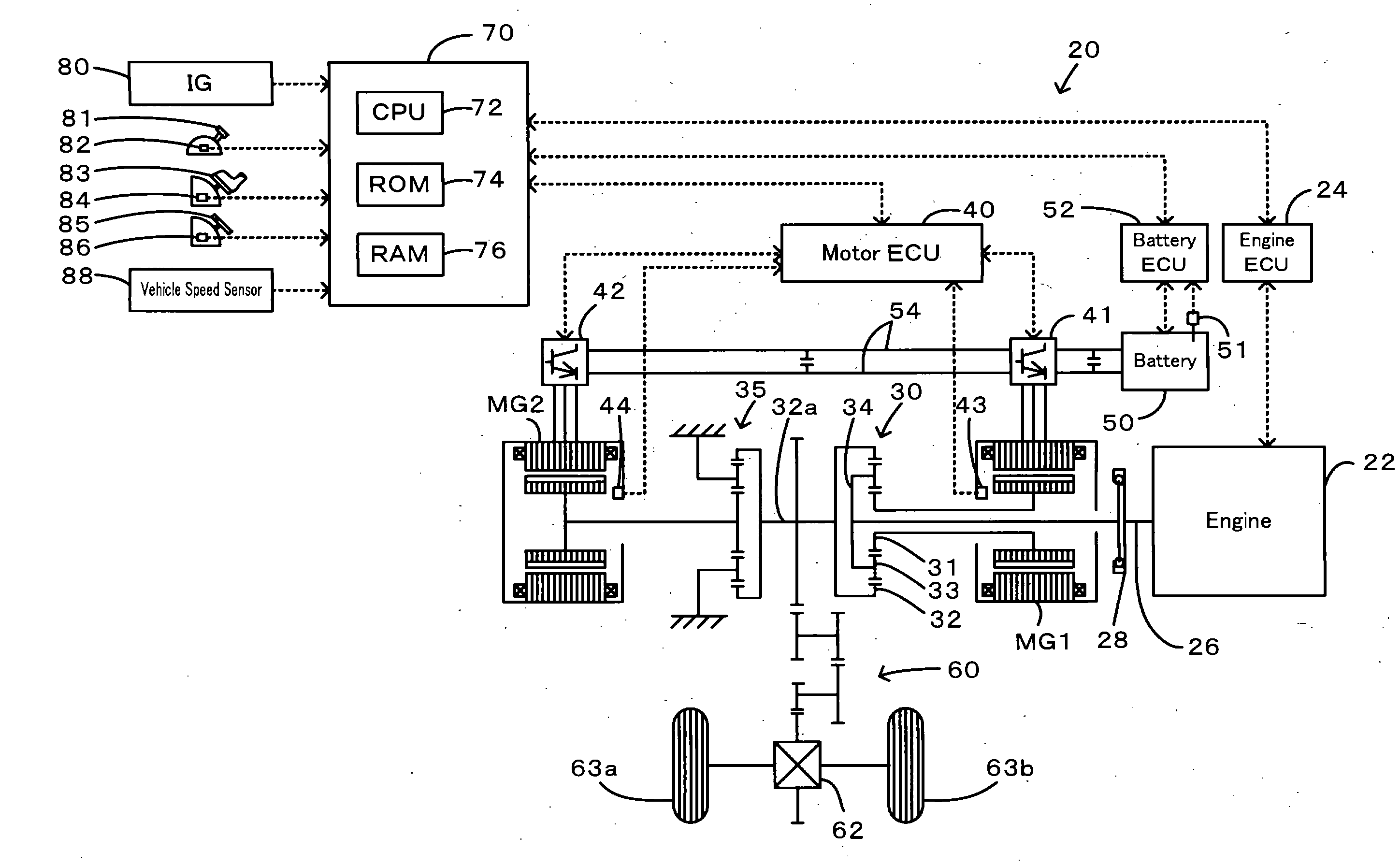
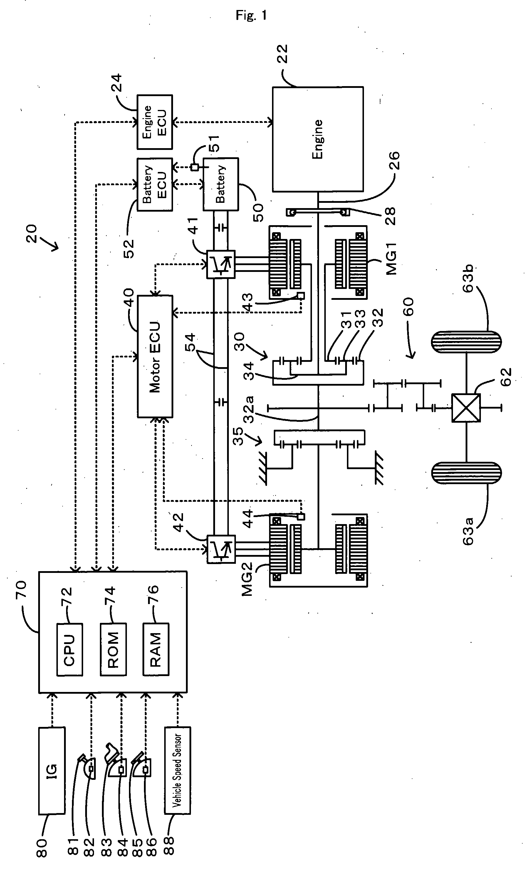
[0034]One mode of carrying out the invention is discussed below as a preferred embodiment. FIG. 1 schematically illustrates the construction of a hybrid vehicle 20 with a power output apparatus mounted thereon in one embodiment of the invention. As illustrated, the hybrid vehicle 20 of the embodiment includes an engine 22, a three shaft-type power distribution integration mechanism 30 that is linked with a crankshaft 26 functioning as an output shaft of the engine 22 via a damper 28, a motor MG1 that is linked with the power distribution integration mechanism 30 and is capable of generating electric power, a reduction gear 35 that is attached to a ring gear shaft 32a functioning as a drive shaft connected with the power distribution integration mechanism 30, another motor MG2 that is linked with the reduction gear 35, and a hybrid electronic control unit 70 that controls the whole power output apparatus.

[0035]The engine 22 is an internal combustion engine that uses a hydrocarbon fue...


PUM


Abstract

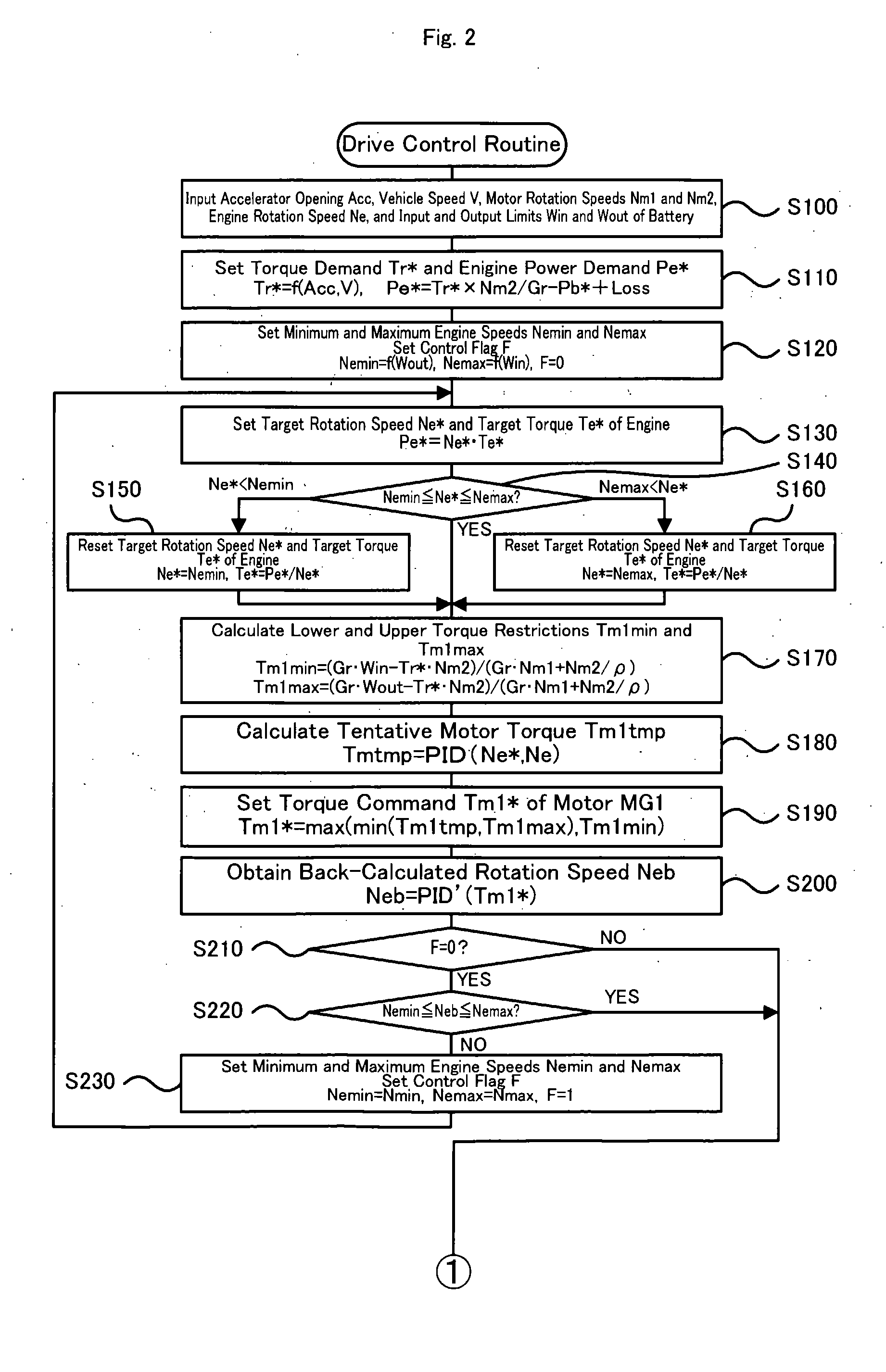
The drive control process of the invention sets minimum and maximum control rotation speeds Necmin and Necmax, which are based on an output limit Wout and an input limit Win of a battery, to a minimum engine speed Nemin and a maximum engine speed Nemax of an engine (step S120). When output of a torque demand Tr* to a driveshaft is attainable through input and output of energies from and to a rotation system including the engine in the range of the input limit Win and the output limit Wout of the battery with limitation of a rotation speed Ne of the engine to the range of the minimum control rotation speed Necmin and the maximum control rotation speed Necmax, the drive control process performs the control to ensure output of the torque demand Tr* to the driveshaft in the range of the minimum control rotation speed Necmin and the maximum control rotation speed Necmax (steps S130 to S200). When the output of the preset torque demand Tr* to the driveshaft is unattainable with limitation of the rotation speed Ne of the engine to the range of the minimum control rotation speed Necmin and the maximum control rotation speed Necmax, on the other hand, the drive control process sets a performance-based minimum rotation speed Nmin and a performance-based maximum rotation speed Nmax to the minimum engine speed Nemin and the maximum engine speed Nemax of the engine (step S230) and repeats the series of control (steps S130 to S200). The range of the performance-based minimum rotation speed Nmin and the performance-based maximum rotation speed Nmax is wider than the range of the minimum control rotation speed Necmin and the maximum control rotation speed Necmax. The drive control process then outputs a torque equivalent to the torque demand Tr* to the driveshaft in the range of the input limit Win and the output limit Wout of the battery.

Description

TECHNICAL FIELD[0001]The present invention relates to a power output apparatus, a control method of the power output apparatus, and a vehicle equipped with the power output apparatus.BACKGROUND ART[0002]One proposed structure of a power output apparatus includes an engine, a planetary gear unit including a carrier and a ring gear respectively connected with a crankshaft of the engine and with a driveshaft mechanically linked to an axle of a vehicle, a first motor arranged to input and output power from and to a sun gear of the planetary gear unit, a second motor arranged to input and output power from and to the driveshaft, and a battery designed to transmit electric power to and from the first motor and the second motor (see, for example, Japanese Patent Laid-Open Gazette No. 2005-39880). This proposed power output apparatus inputs and outputs a power from and to the driveshaft via the ring gear based on the power input from the engine to the carrier and the power input from the fi...

Claims


Application Information

Patent Timeline
IPC IPC(8): B60K6/20B60L15/20G06F19/00B60K6/445B60K6/448B60K6/52B60L50/16B60W10/00B60W10/04B60W10/06B60W10/08B60W10/12B60W10/26B60W20/00F02D29/02F02D29/06
CPCB60K6/445Y10T477/23B60W10/08B60W10/26B60W20/00B60W30/188B60W2510/244B60W2510/246B60W2710/0644Y02T10/6286Y02T10/7258B60L11/123B60L11/14Y02T10/6239Y02T10/7077Y02T10/7005Y02T10/6217B60W10/06B60L50/61B60L50/16Y02T10/62Y02T10/7072Y02T10/72Y02T10/70B60W20/13
Inventor HASHIMOTO, TOSHIYA
Owner TOYOTA JIDOSHA KK
Learn More