Wheel-driven battery charger

a technology of generators and chargers, which is applied in the direction of electric generator control, electric propulsion mounting, electric devices, etc., can solve the problems of generators imposing significant drag on the vehicle, offering generally poor performance in the low-speed environment of horse-drawn vehicles, and enhancing vehicle safety. , the effect of easy integration

Inactive Publication Date: 2008-11-27
STOLTZFUS JOHN
View PDF23 Cites 42 Cited by
  • Summary
  • Abstract
  • Description
  • Claims
  • Application Information

AI Technical Summary

Benefits of technology

[0012]It is a still further object of the present invention to provide a battery charging system for a non-motorized vehicle capable of powering on on-board lighting system thereby enhancing vehicle safety while operating on public roadways during non-daylight conditions.
[0013]It is a still further object of the present invention to provide a wheel-driven generator for a battery charging system on a horse-drawn vehicle that can be easily integrated into an existing wheel hub design that does not require alteration of the wheel hub.
[0014]It is a still further object of the present invention to provide a wheel-driven battery charging system that can be selectively configured to provide regenerative braking for the vehicle.
[0015]It is a still further object of the present invention to provide a wheel-driven battery charging system for an animal drawn vehicle that is durable in construction, inexpensive of manufacture, carefree of maintenance, easily assembled, and simple and effective to use.
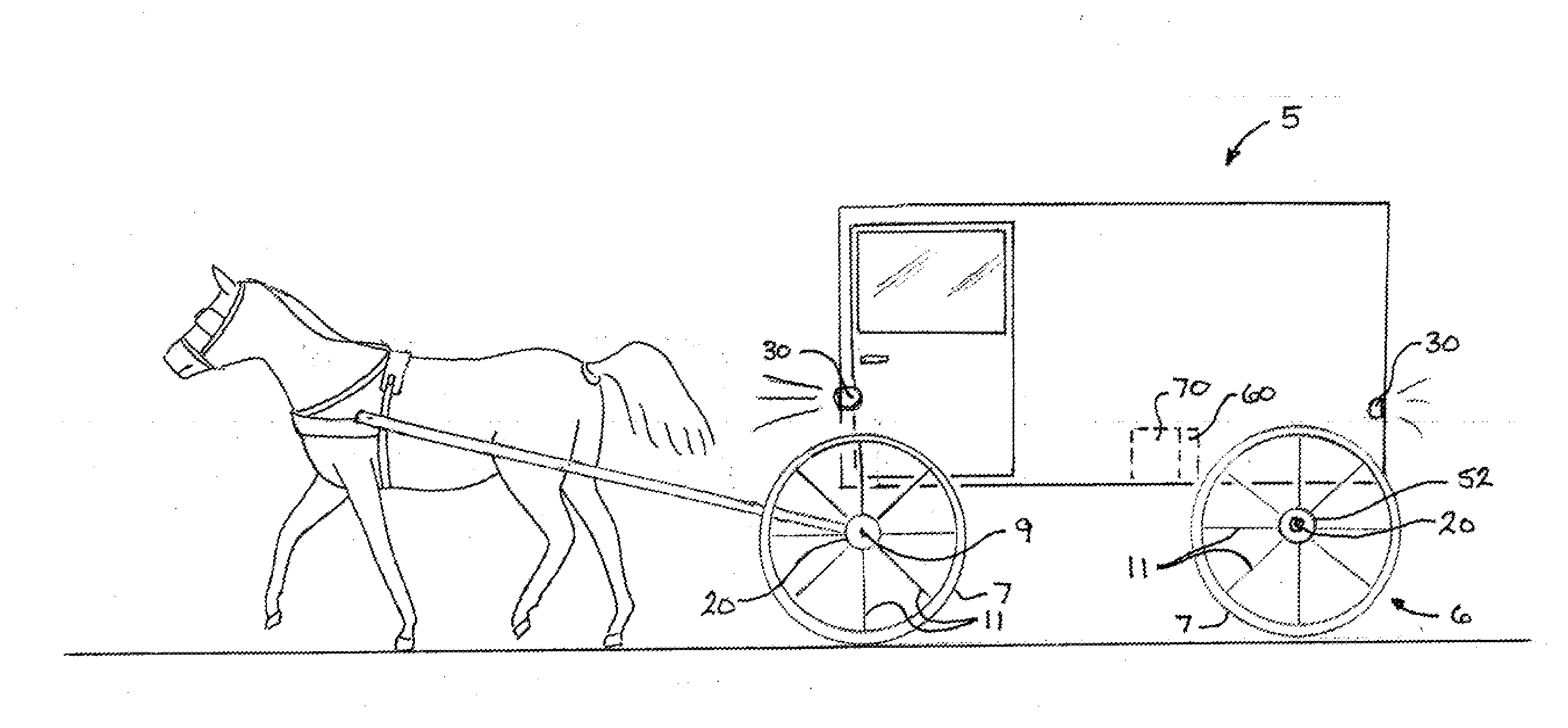
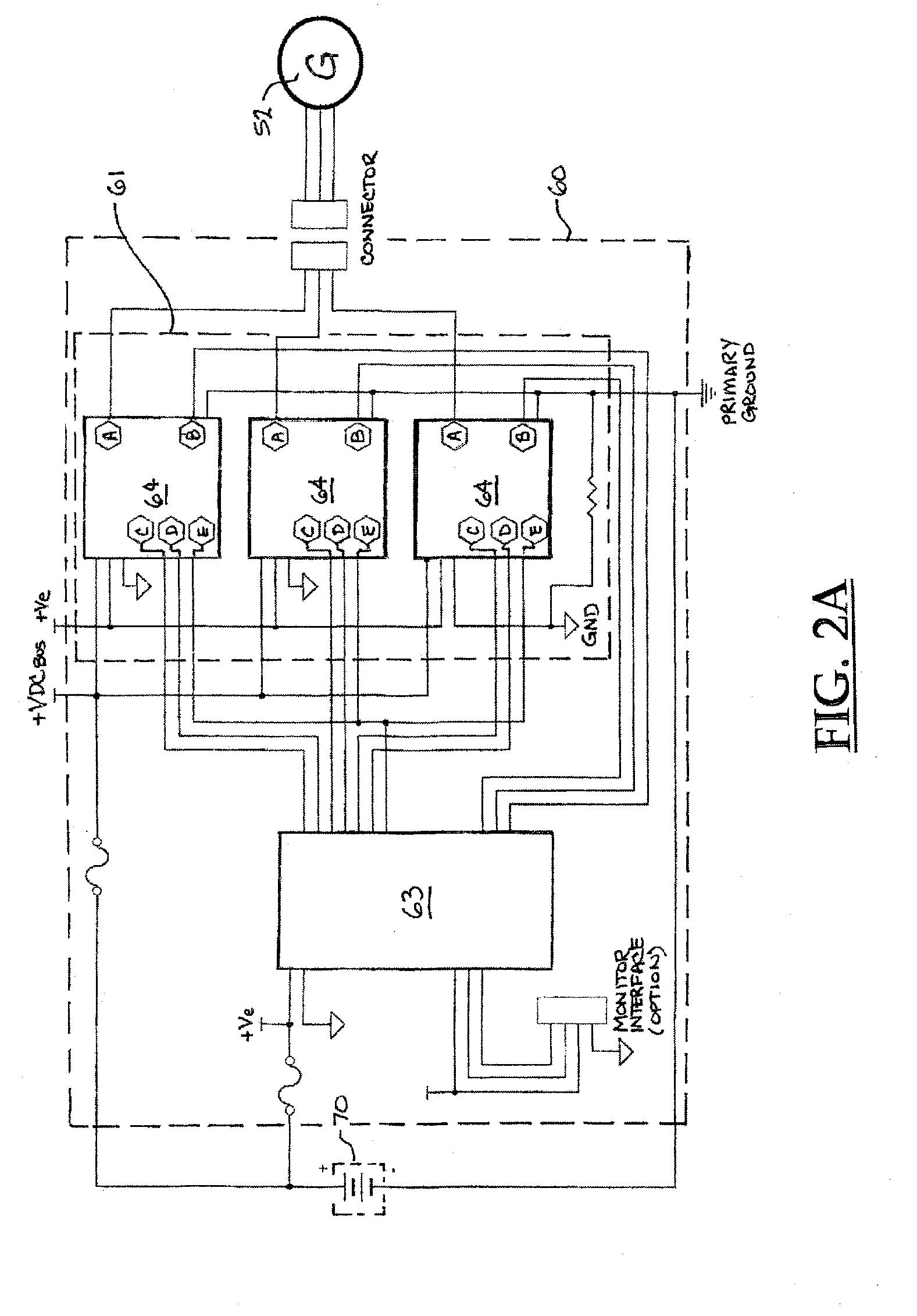
[0016]These and other objects are achieved by providing an improved battery charging system for use on a non-motorized, ground-supported wheeled vehicle, such as a horse-drawn buggy, including a generator incorporated into the hub assembly of at least one wheel., a voltage regulator for controlling the voltage output of the generator over the full range or vehicle speeds and a battery. The synchronous generator features rare earth metal permanent magnets arranged in a three-phase, outside rotor disposed within a wheel brake housing of a buggy wheel hub. The stator is situated on an axle. Voltage regulation includes active switching whereby generator output voltage is rectified only during tow vehicle speed operation to provide a charging current to a battery and where voltage is actively managed as vehicle speed increases to maintain voltage levels within predefined limits to prevent damage to the connected battery.

Problems solved by technology

Lighting run times are limited due to the inconvenience of recharging the battery.
Operators of these non-motorized vehicles wanting some form of on-vehicle battery charging are forced to rely on poorly adapted automotive-style battery charging systems which offer generally poor performance in the low-speed environment of a horse-drawn vehicle.
These types of generators generally impose significant drag on the vehicle relative to the power output provided.
The rotational interface between the vehicle wheels and the generator is also susceptible to failure.
Systems using belts or chains to transfer rotational motion to the generator input shaft introduce complexity to the system and may result in an apparatus that is failure-prone under harsh conditions or without frequent maintenance.
Non-motorized vehicles are generally limited in their maximum speed, but may experience a wide range of operational speeds.
This presents two significant challenges for a generator used to charge a battery.
The first challenge is generating sufficient power and voltage at relatively low vehicle speeds, as low as a 1 mph.
The second challenge presented is limiting voltage and power of the efficient low speed optimized generator at relatively high vehicle speeds ranging from 10 to 25 mph.
A generator efficient at low speed will produce voltages exceeding the upper limits of battery charging and potentially damage the battery, charging circuit, or both.
The practice decreases efficiency of the system and limits the total power output of the generator system.

Method used


Image

  • Wheel-driven battery charger
  • Wheel-driven battery charger
  • Wheel-driven battery charger

Examples


Embodiment Construction

)

[0026]Many of the fastening, connections processes and other means and components utilized in this invention are widely known and used in the field of the invention described, and their exact nature or type is not necessary for an understanding and use of the invention by a person skilled in the art and they will not therefore be discussed in significant detail. Also., any reference herein to the terms “left” or “right,”“up” or “down,” or “top” or “bottom” are used as a matter of mere convenience, and are determined by standing at the rear of the vehicle facing in its normal direction of travel. Furthermore, the various components shown or described herein for any specific application of this invention can be varied or altered as anticipated by this invention and the practice of a specific application of any element may already be widely known or used in the art by persons skilled in the art and each will likewise not therefore be discussed in significant detail. When referring to ...


PUM


Abstract

An improved battery charging system for use on a non-motorized, ground-supported wheeled vehicle such as a horse-drawn buggy, including a generator incorporated into the hub assembly of at least one wheel, a voltage control unit for controlling the voltage output of the generator over the full range or vehicle speeds, and a battery. The synchronous generator features rare earth metal permanent magnets arranged in a three-phase, outside rotor disposed within a wheel brake housing of a buggy wheel hub. The stator is situated on an axle. Voltage regulation includes active switching whereby generator output voltage is rectified during low vehicle speed operation and an increasing portion directed away from the battery as vehicle speed and thus generator output voltage increases to a level which could damage the connected battery.

Description

BACKGROUND OF THE INVENTION[0001]The present invention relates generally to a generator and control apparatus for charging a battery and more particularly to a non-friction, wheel-driven generator for charging a battery on a non-motorized wheeled vehicle.[0002]The use of horse-drawn vehicles as a means of transportation continues today in surprising numbers. One significant constituency relying on horse-drawn vehicles as a means of transportation is people observing certain practices as a means of maintaining their religious beliefs. Many “plain sect” religions (Anabaptist), including Amish and Mennonite, eschew motorized vehicles in favor of horse-drawn carriages, buggies, and wagons in support of their religious practices. As these vehicles are routinely used on public roads, they are required to have certain safety equipment. Nighttime operation requires the use of lights, both forward aimed to illuminate the road ahead and allow the vehicle to be seen, and rearward aimed to aler...

Claims


Application Information

Patent Timeline
Patent Type & Authority Applications(United States)
IPC IPC(8): B60L1/00
CPCH02K7/1846H02P2101/45H02P9/48
Inventor STOLTZFUS, JOHN
Owner STOLTZFUS JOHN
Why Eureka
Try Eureka