Technique of Motion Estimation When Acquiring An Image of A Scene That May Be Illuminated With A Time Varying Luminance

a technology of motion estimation and scene illumination, applied in the field of image motion estimation, can solve the problems of reducing the depth of field and increasing optical blur, reducing the noise within the image, and reducing so as to reduce the effect of varying object scene illumination and reduce the effect of motion estimation, or even eliminate the

Active Publication Date: 2008-11-27
QUALCOMM INC
View PDF10 Cites 26 Cited by
  • Summary
  • Abstract
  • Description
  • Claims
  • Application Information

AI Technical Summary

Benefits of technology

[0011]Therefore, in order to reduce the effect of the varying object scene illumination as a factor causing error in image motion estimations, the data of the two acquired images are normalized, and the normalized values are then used to calculate a motion estimate. In a preferred implementation, the normalization includes calculating a mean value of pixels for each of many blocks of pixels in both of the two images and then arithmetically combining the mean value with the values of individual pixels in the block, such as subtracting one from the other. The normalized pixel values are then used to estimate motion in an otherwise conventional manner, such as by use of a sum of absolute differences (SAD) algorithm. Instead of the actual values of the pixels, the mean normalized values are used to estimate motion. This significantly reduces, or even eliminates, the effects on the motion estimate of a varying illumination of the object scene during acquisition of the image frames used to calculate motion.

Problems solved by technology

An increased aperture results in an image with a reduced depth of field and increased optical blur, and increasing the gain causes the noise within the image to increase.
Conversely, when the exposure time can be increased, the aperture and / or gain are reduced, which results ill the image having a greater depth of field and / or reduced noise.
It is often difficult for the user to hold a camera by hand during an exposure without imparting some degree of shake or jitter, particularly when the camera is very small and light.
As a result, the captured image may have a degree of overall motion blur that depends on the exposure time, the longer the time the more motion blur in the image.
In addition, long exposures of a scene that is totally or partially moving can also result in motion blur in the captured image.
One difficulty with existing techniques for calculating motion vectors is that illumination of the object scene with a varying illumination can be misinterpreted as image motion.
If the intensity of illumination of the object scene is one level when the first image frame is acquired and a significantly different level when the second image frame is acquired, motion estimated from the data of these two frames will most likely be erroneous.
But if not, it is determined that no motion estimate can be made for the portion of the image, rather than use the result of the SAD algorithm which may not be correct in that case.

Method used


Image

  • Technique of Motion Estimation When Acquiring An Image of A Scene That May Be Illuminated With A Time Varying Luminance
  • Technique of Motion Estimation When Acquiring An Image of A Scene That May Be Illuminated With A Time Varying Luminance
  • Technique of Motion Estimation When Acquiring An Image of A Scene That May Be Illuminated With A Time Varying Luminance

Examples


Embodiment Construction

Electronic Camera Example

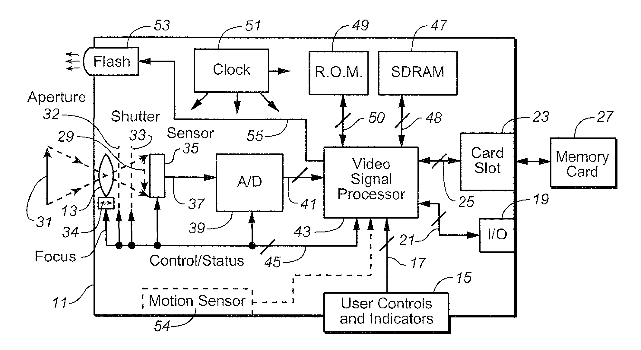
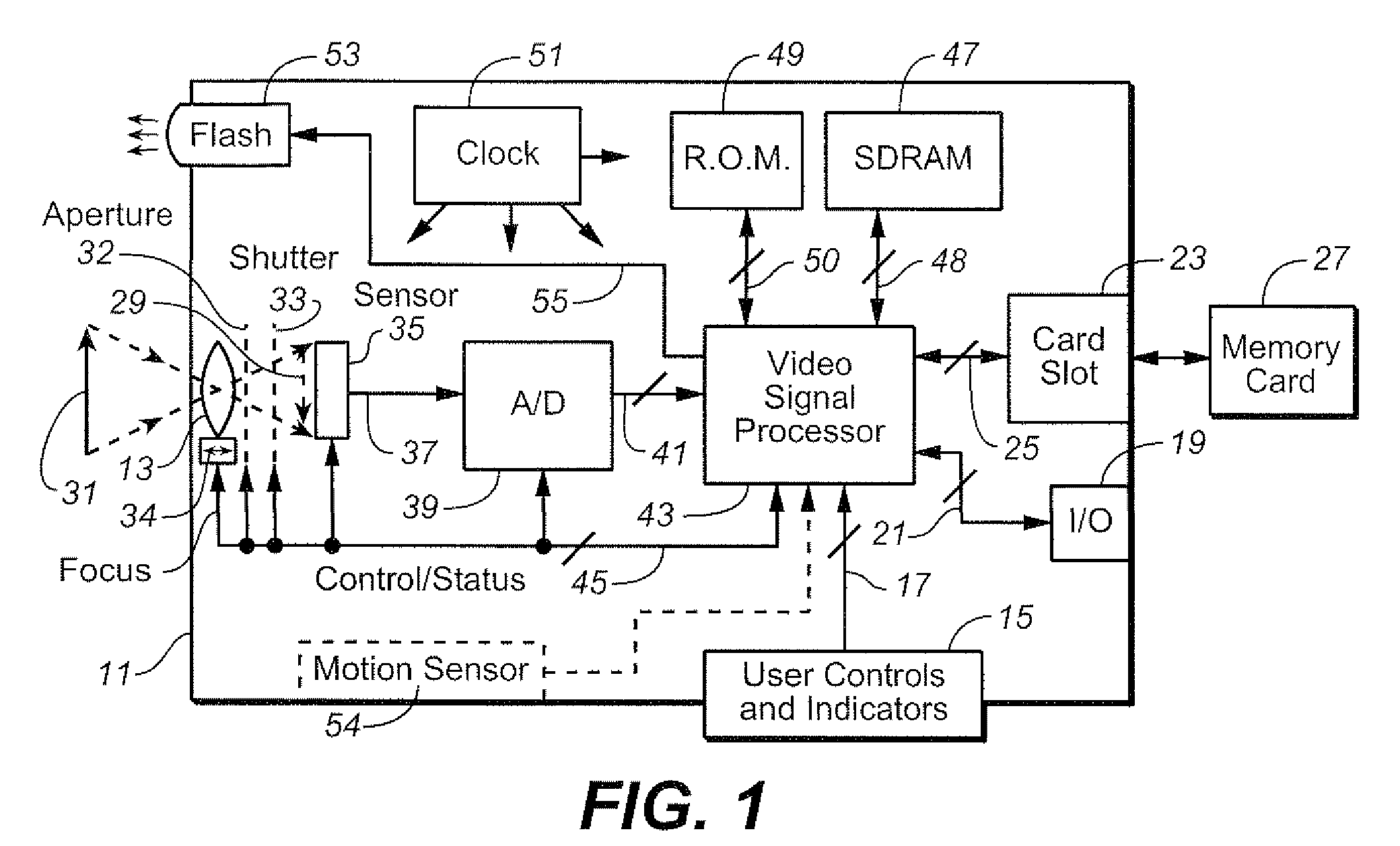
[0022]In FIG. 1, an example of a camera in which the motion estimation techniques described herein may be implemented is schematically shown, which may be a still camera or a video camera. It includes a case 11, an imaging optical system 13, user controls and indicators 15 that generate and receive control signals 17, a video input-output receptacle 19 with internal electrical connections 21, and a card slot 23, with internal electrical connections 25. A non-volatile memory card 27 is removably inserted into the card slot 23. Data of images captured by the camera may be stored on the memory card 27 or in an internal non-volatile memory (not shown). Image data may also be outputted to another video device through the receptacle 19. The memory card 27 can be a commercially available semiconductor flash memory, small removable rotating magnetic disk or other non-volatile memory to which video data can be written by the camera.

[0023]The optical system 13 can be ...


PUM


Abstract

In a digital camera or other image acquisition device, motion vectors between successive image frames of an object scene are calculated from normalized values of pixel luminance in order to reduce or eliminate any effects on the motion calculation that might occur when the object scene is illuminated from a time varying source such as a fluorescent lamp. Calculated motion vectors are checked for accuracy by a robustness matrix.

Description

BACKGROUND AND SUMMARY[0001]This application relates to the automatic operation of digital cameras and other electronic digital image acquisition devices, and particularly to the estimation of image motion between successive image frames.[0002]Electronic cameras image scenes onto a two-dimensional sensor such as a charge-coupled-device (CCD), a complementary metal-on-silicon (CMOS) device or other type of light sensor. These devices include a large number of photo-detectors (typically four, six, eight or more million) arranged across a small two dimensional surface that individually generate a signal proportional to the intensity of light or other optical radiation (including infrared and ultra-violet regions of the spectrum adjacent the visible light wavelengths) striking the element. These elements, forming pixels of an image, are typically scanned in a raster pattern to generate a serial stream of data representative of the intensity of radiation striking one sensor element after...

Claims


Application Information

Patent Timeline
Patent Type & Authority Applications(United States)
IPC IPC(8): H04N5/228H04N5/335H04N5/235
CPCH04N5/23248H04N5/23254H04N5/2351H04N23/6811H04N23/68H04N23/71
Inventor TZUR, MEIRPINTO, VICTORPINHASOV, ERAN
Owner QUALCOMM INC
Why Eureka
Try Eureka