Monolithic ceramic capacitor

a monolithic ceramic capacitor and monolithic ceramic technology, applied in the direction of fixed capacitors, stacked capacitors, fixed capacitor details, etc., can solve the problems of inability to operate circuits, decrease the capacitance corresponding to the “inverse of the number of arrays”, and the capacitance may therefore be significantly reduced, so as to achieve the effect of effectively reducing esl and fine adjustment of the overall capacitance of monolithic ceramic capacitors

Active Publication Date: 2008-11-27
MURATA MFG CO LTD
View PDF13 Cites 15 Cited by
  • Summary
  • Abstract
  • Description
  • Claims
  • Application Information

AI Technical Summary

Benefits of technology

[0048]In preferred embodiments of the present invention, the monolithic ceramic capacitor may further include a second same-polarity-connection conductor. In this case, the second same-polarity-connection conductor achieves advantageous effects that are substantially similar to those achieved by the first same-polarity-connection conductor described above.
[0049]In this case, the first same-polarity-connection conductor may include a same-polarity-connection conductor that is arranged so as to face the first and third internal electrodes through the ceramic layer and that is arranged so as to face the second same-polarity-connection conductor, on a side opposite to a side on which the first and third internal electrodes are located, through the ceramic layer. Thus, no capacitance is generated between the same-polarity-connection conductors and the internal electrodes while a capacitanc

Problems solved by technology

In a power supply circuit, an increase in voltage variations in a power supply line due to the presence of impedance in the power supply line or a ground may cause an unstable operation of circuits, interference between the circuits through the power supply circuit, or oscillation.
First, in a monolithic ceramic capacitor which is mounted on a wiring substrate via solder joints, due to a defect, such as cracking of a solder joint, a disconnection may occur between a certain external terminal elec

Method used


Image

  • Monolithic ceramic capacitor
  • Monolithic ceramic capacitor
  • Monolithic ceramic capacitor

Examples


Embodiment Construction

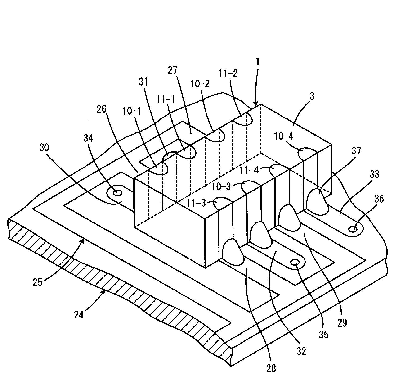
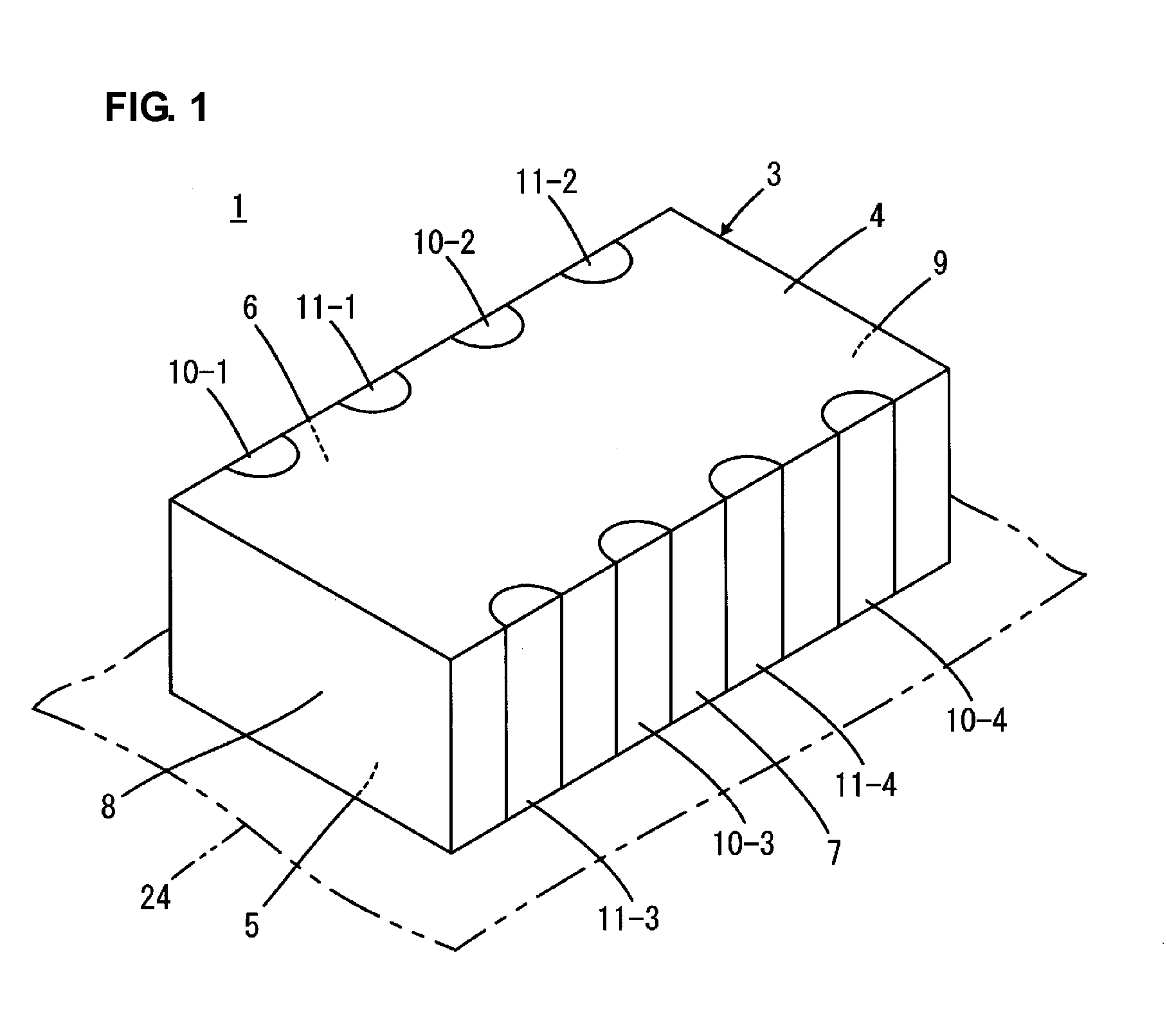
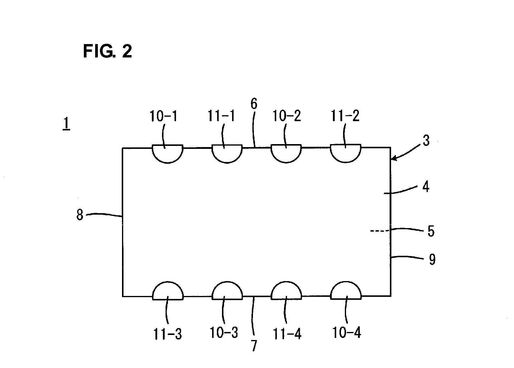
[0066]FIGS. 1 to 4 show a monolithic ceramic capacitor 1 according to a first preferred embodiment of the present invention. FIG. 1 is a perspective view showing an external appearance of the monolithic ceramic capacitor 1, and FIG. 2 is a plan view showing the external appearance of the monolithic ceramic capacitor 1. FIGS. 3A to 3D are plan views showing an internal structure of the monolithic ceramic capacitor 1 in cross section, showing a lamination order from the top layer. FIG. 4 is a perspective view showing how the monolithic ceramic capacitor 1 shown in FIG. 1 is mounted.

[0067]The monolithic ceramic capacitor 1 preferably includes a substantially rectangular parallelepiped capacitor body 3 having a plurality of laminated ceramic layers 2. Each of the ceramic layers 2 is preferably made of, for example, a dielectric ceramic including, as a main component, BaTiO3, CaTiO3, SrTiO3, CaZrO3, or other suitable main component. An auxiliary component, such as a Mn compound, an Fe co...


PUM

PropertyMeasurementUnit
Timeaaaaaaaaaa
Polarityaaaaaaaaaa
Electrical inductanceaaaaaaaaaa

Abstract

A multi-terminal monolithic ceramic capacitor arranged to reduce an equivalent series inductance and having an array structure is provided. A first same-polarity-connection conductor and a second same-polarity-connection conductor are provided inside a capacitor body so as to extend over at least two capacitors. The first same-polarity-connection conductor is electrically connected to a plurality of first external terminal electrodes, and the second same-polarity-connection conductor is connected to a plurality of second external terminal electrodes. In the monolithic ceramic capacitor which is mounted on a wiring substrate, the overall capacitance can be maintained even if an accident, such as cracking of a solder joint, occurs in one of the external terminal electrodes.

Description

BACKGROUND OF THE INVENTION[0001]1. Field of the Invention[0002]The present invention relates to a monolithic ceramic capacitor. More specifically, the present invention relates to a multi-terminal monolithic ceramic capacitor arranged to reduce an equivalent series inductance (ESL).[0003]2. Description of the Related Art[0004]In a power supply circuit, an increase in voltage variations in a power supply line due to the presence of impedance in the power supply line or a ground may cause an unstable operation of circuits, interference between the circuits through the power supply circuit, or oscillation. In order to address such problems, a decoupling capacitor is typically connected between the power supply line and the ground. The decoupling capacitor reduces the impedance between the power supply line and the ground to suppress variations in power supply voltage or interference between the circuits.[0005]Recently, in communication devices, such as mobile phones, or information pr...

Claims


Application Information

Patent Timeline
IPC IPC(8): H01G4/228H01G4/12
CPCH01G4/228H01G4/385H01G4/12H01G4/30
Inventor TAKASHIMA, HIROKAZUUEOKA, HIROSHITAKAGI, YOSHIKAZU
Owner MURATA MFG CO LTD
Why Eureka
Try Eureka