Carbon Foam Core Panels

Inactive Publication Date: 2008-11-27
GRAFTECH INT HLDG INC
View PDF0 Cites 30 Cited by
  • Summary
  • Abstract
  • Description
  • Claims
  • Application Information

AI Technical Summary

Problems solved by technology

Decking for naval vessels and the like presents unique challenges.
In addition, metallic decking transmits heat and vibration, requiring specialized dampeners and other materials to be employed, at significant cost, and added weight.
While composite laminates of for example, foams and wood products, have been suggested for decking applications, a composite having the required strength to weight ratio has not yet been found feasible.
Added to this is the fact that laminate sandwiches developed to date are prone to failure throug

Method used


Image

  • Carbon Foam Core Panels
  • Carbon Foam Core Panels
  • Carbon Foam Core Panels

Examples


Embodiment Construction

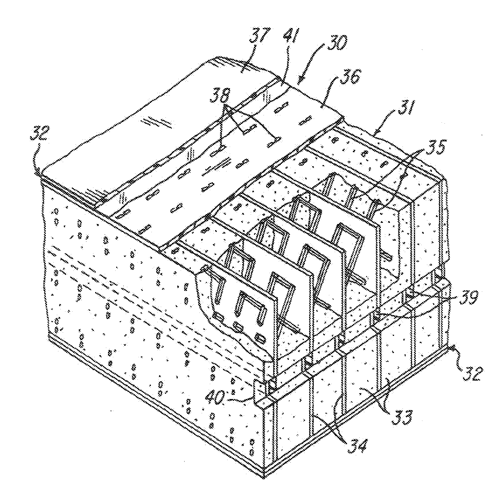
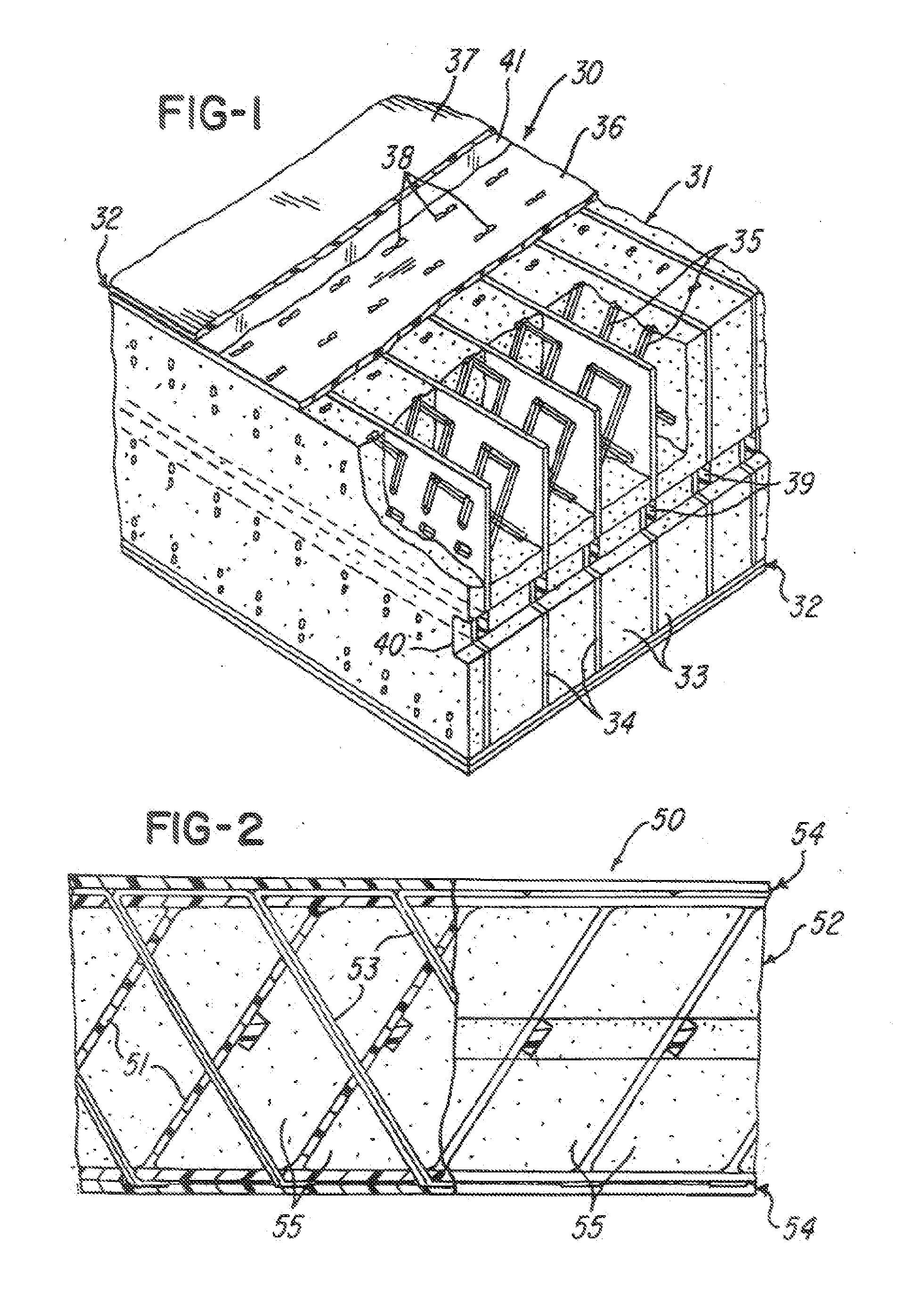
[0058]FIG. 1 illustrates a structural composite sandwich panel 30 which may be used, for example, as the floor of a highway truck cab, the hull or transom of a boat, the roof of a factory building, or as a vehicular or pedestrian bridge deck. Panel 30 comprises a fiber reinforced carbon foam core 31 and opposing fiber reinforced skins 32. Foam core 31 comprises a one or more foam strips 33, preferably a plurality of foam strips 33.

[0059]The core reinforcing fibers, which are selected to impart structural properties to the core, are of fiberglass or carbon fiber or other reinforcing fibers. In one direction, the reinforcing fibers comprise a plurality of parallel sheets or webs 34 of porous, fibrous fabric or mat which extend between the faces of the core 31 and which have been adhesively attached to one face of each foam strip 33 while maintaining substantial porosity in the web material. If desired, the webs 34 may incorporate reinforcements comprising a plurality of individual rov...


PUM

PropertyMeasurementUnit
Fractionaaaaaaaaaa
Fractionaaaaaaaaaa
Diameteraaaaaaaaaa

Abstract

The core panel includes a plurality of carbon foam blocks. One or more of the blocks have a cell volume wherein at least about 90% of the cells have a diameter of between at least about 10 microns and about 150 microns. Also at least about 1% of the cell volume of the block has cells having a diameter of about 0.8 microns to about 3.5 microns.

Description

RELATED APPLICATION[0001]This application is a continuation-in-part of copending and commonly assigned U.S. Application having Ser. No. 11 / 367,776, filed in the names Miller, Lewis, and Shao, on Mar. 3, 2006, entitled Laminated Carbon Foam Sandwich for Naval Decking, of which is a continuation in part of commonly assigned U.S. Application having the Ser. No. 10 / 970,352, filed in the names of Miller, Lewis and Mercuri on Oct. 21, 2004, entitled “High Strength Monolithic Carbon Foam,” the disclosures of which are incorporated herein by reference in their entirety.BACKGROUND OF THE INVENTION[0002]1. Technical Field[0003]The present invention relates to a laminated high strength monolithic carbon foam material that is especially useful for the production of decking for naval vessels and the like. More particularly, the present invention relates to reinforced carbon foam sandwiched between two composite facesheets, and exhibiting improved strength, weight and density characteristics desi...

Claims


Application Information

Patent Timeline
IPC IPC(8): B32B3/26
CPCC04B38/0032Y10T428/30C04B35/524C04B38/0054C04B38/0067C04B38/0074C04B35/83Y10T428/249978
Inventor MILLER, DOUGLAS J.LEWIS, IRWIN C.SHAO, RICHARD L.SEGGER, MARK
Owner GRAFTECH INT HLDG INC
Why Eureka
Try Eureka