Variable flow rate dehumidification plant and process for granular materials

a granular material, variable flow rate technology, applied in the direction of drying machines with progressive movements, separation processes, furnaces, etc., can solve the problems of blowholes and non-homogeneity in the structure and color of manufactured items, inability to continuously carry out the process, and surface defects, etc., to achieve the effect of dehumidifying granular plastic materials

Active Publication Date: 2008-12-04
MORETTO SPA
View PDF13 Cites 12 Cited by
  • Summary
  • Abstract
  • Description
  • Claims
  • Application Information

AI Technical Summary

Benefits of technology

[0009]The main object, therefore, of the present invention is that of providing a dehumidification plant suitable for effectively dehumidifying granular plastic material with an energy consumption less than that of the dehumidification processes proposed up to now.
[0011]Another object of the present invention is that of providing a regeneration process of a tower in a dehumidification plant that requires lower costs and energy consumptions than known processes.

Problems solved by technology

Such granules, nevertheless, being hygroscopic, usually contain water molecules, absorbed during previous workings, which when the granules are subjected to melting can enter the molecular chains of the polymers.
This leads to the formation of surface defects, blowholes and non-homogeneity both in the manufactured item's structure and color.
The absorbent means proposed up to now, nevertheless, have a limited absorption capacity, and if the dehumidification process was achieved by means of a plant comprising a single tower filled with absorbent means, the process could not be continuously carried out, but would be subjected to frequent and prolonged interruptions necessary for desorbing water from the absorbent means.
Such dehumidification plants, even if they allow good continuous dehumidification of the granular plastic material to be obtained, require a high amount of energy, particularly required for producing dry air intended to dehumidify the absorbent means.

Method used


Image

  • Variable flow rate dehumidification plant and process for granular materials
  • Variable flow rate dehumidification plant and process for granular materials

Examples


Embodiment Construction

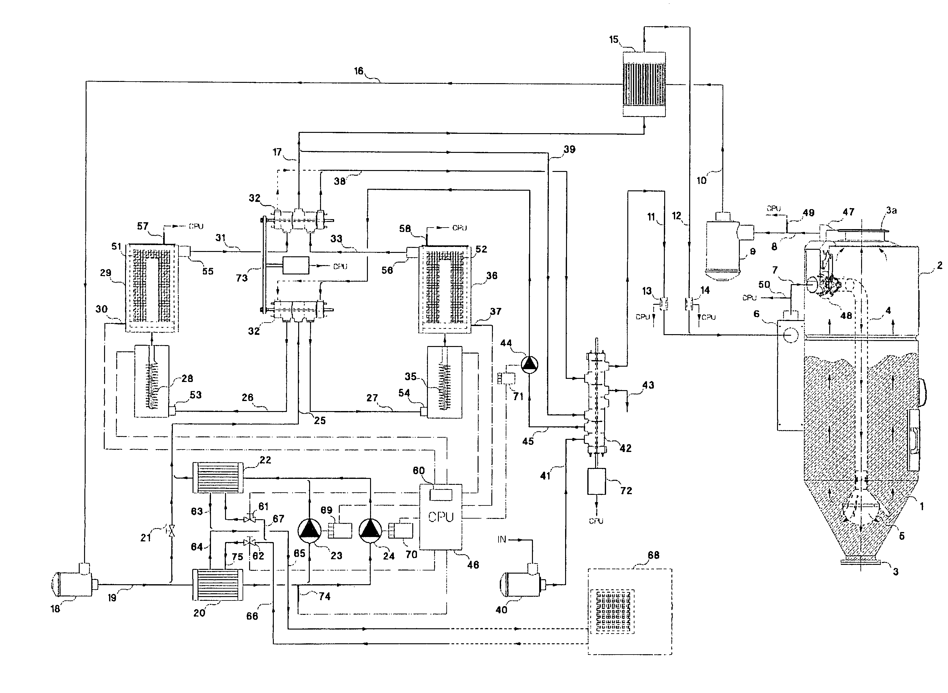
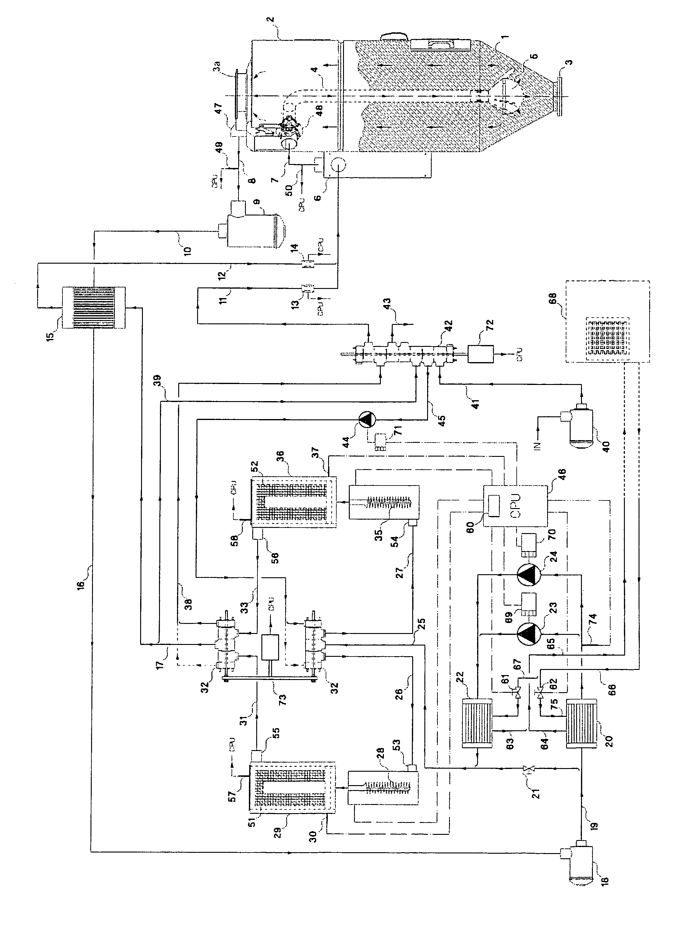
[0017]With specific reference to the FIGURE in the drawing, a dehumidification plant according to the present invention comprises one or more hoppers 2, in which granular material 1 to be dehumidified by means of a gas current, e. g. air, is loaded, and two towers 29, 36, in which the moisture of the air is absorbed. The plastic granular material is dehumidified by the air, the two towers being alternately one in a processing phase (in which the tower is crossed by an air current to be dehumidified) and the other in a regeneration phase of the absorbent material contained therein, as occurs with conventional plants. Each hopper 2 comprises an upper loading mouth 3a for the granular material 1 and a lower discharge mouth 3, at which a meter or extractor device is provided (not shown in the FIGURE) of any suitable type.

[0018]At an upper zone (in use) of each hopper 2, an inlet mouth 48 is provided for hot and dry air, from which a duct 4 departs towards the interior of the hopper 2, d...


PUM

PropertyMeasurementUnit
temperatureaaaaaaaaaa
humidityaaaaaaaaaa
rotation speedaaaaaaaaaa

Abstract

The present invention relates to a dehumidification plant for a granular material, comprising at least one hopper (2) having at least one loading mouth (3a) and one discharge mouth (3) for granular material, at least one upper feeding mouth in the at least one hopper (2) and at least one lower delivery mouth of a gaseous medium therefrom, humidity absorbent means (51, 52) designed to absorb the humidity conveyed by the gaseous medium; at least two towers (29, 36) arranged to contain the absorbent means (51, 52); supplying means designed to feed the gaseous medium to the at least one hopper (2) and the at least two towers (29, 36); at least one electronic control unit (46); detection means arranged to detect process variables of the plant and electrically connected with the at least one electronic control unit (46). The plant further comprises distribution means designed to distribute gaseous medium coming from at least one (29, 36) of the at least two towers thereby feeding it to at least another tower (36, 29) from among the at least two towers, the distribution means being controllable by the at least one electronic control unit (46) between at least one open position, in which at least one portion of the gaseous medium contained in the at least one of the at least two towers (29, 36) is fed to the at least another (36, 29) of the at least two towers, and at least one closed position.

Description

FIELD OF INVENTION[0001]The present invention regards a dehumidification plant and process for hygroscopic materials, particularly suitable for granular materials, e. g. plastic materials.BACKGROUND OF INVENTION[0002]As is known, granules of polymer-based plastic materials that are used for making manufactured products or the like must be subjected to a melting process. Such granules, nevertheless, being hygroscopic, usually contain water molecules, absorbed during previous workings, which when the granules are subjected to melting can enter the molecular chains of the polymers. This leads to the formation of surface defects, blowholes and non-homogeneity both in the manufactured item's structure and color.[0003]Many dehumidification plants were proposed up to now for granular plastic materials. The most used provide for the use of absorbent means or materials, e. g. molecular sieves, which at room temperature have good absorbent properties towards water molecules, while at much hig...

Claims


Application Information

Patent Timeline
Patent Type & Authority Applications(United States)
IPC IPC(8): F26B21/10F26B21/08F26B21/00F26B3/02F26B19/00
CPCF26B21/083B29B9/16B29B13/065B01D53/02B01D53/14
Inventor MORETTO, RENATO
Owner MORETTO SPA
Why Eureka
Try Eureka