Dispensing device

a technology of a dispensing device and a cylinder head, which is applied in the direction of liquid transferring devices, respirators, transportation and packaging, etc., can solve the problems of inhalable fraction, difficult to transfer and de-agglomerate, stick together, etc., and achieves simple construction, easy handling or operation, and simple construction

Inactive Publication Date: 2008-12-04
BOEHRINGER INGELHEIM INT GMBH
View PDF5 Cites 69 Cited by
  • Summary
  • Abstract
  • Description
  • Claims
  • Application Information

AI Technical Summary

Benefits of technology

[0017]The object of the present invention is to provide an improved dispensing device, in particular wherein a compact construction, easy handling or operation, a high delivery efficiency and / or desired spray plume characteristics can be achieved.
[0029]Preferably, each insert comprises at least one channel and / or nozzle arrangement in order to directly form the spray during use. Thus, the spray is generated by the respective insert when pressurized gas is supplied. This makes it possible to respectively generate sprays with the desired spray plume characteristics with high accuracy.

Problems solved by technology

The problem with passive inhalers is that the inhalable fraction, or the proportion of powder that actually enters the lungs, is largely dependent on the breathing of the patient.
The lactose and / or active drug(s) tend to absorb humidity from the atmosphere, which makes them stick together and difficult to transfer and de-agglomerate.
It is difficult to empty the respective pocket completely during a dispensing operation.
Incomplete emptying results in decreased delivery efficiency.
Some powder may be lost in the inhaler and not dispensed because the known solutions require relatively long paths for the powder until the powder reaches a nozzle and is actually dispensed.
This might reduce the delivery efficiency further.
In addition, de-agglomeration of the powder is difficult.

Method used


Image

  • Dispensing device
  • Dispensing device
  • Dispensing device

Examples


Embodiment Construction

[0048]In the figures, the same reference signs are used for the same or similar parts and components, wherein the same or similar features, aspects and / or advantages are achieved in the different embodiments, even if a repetition of the respective description is omitted.

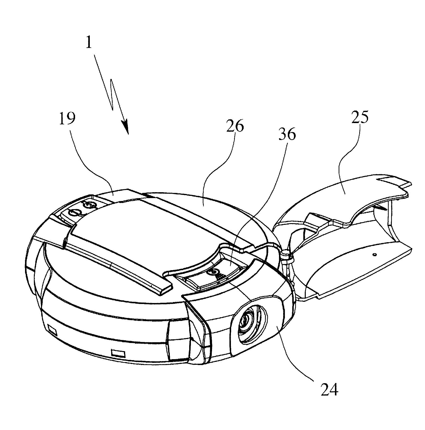
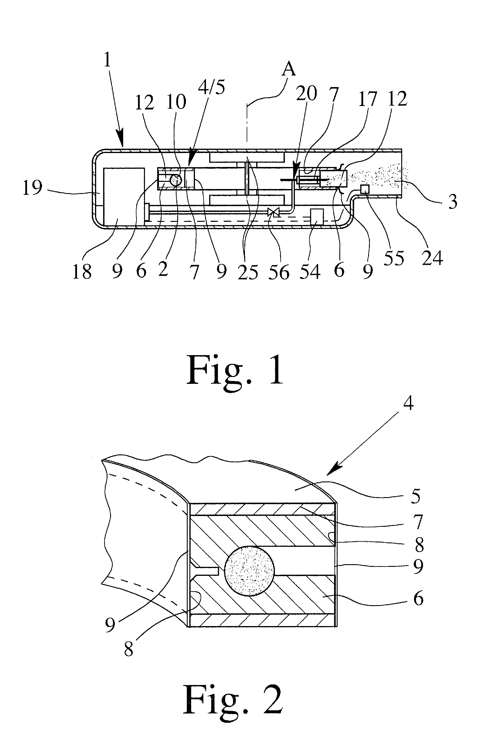
[0049]FIG. 1 shows in a schematic sectional view—for illustration purposes not in scale—a dispensing device 1 according to the present invention. The dispensing device 1 is preferably an active device, in particular, gas powered. Preferably, the dispensing device 1 is an oral or nasal inhaler, in particular a dry powder inhaler, for a user, respectively the patient (not shown).

[0050]Preferably, the dispensing device 1 is portable and / or hand-held.

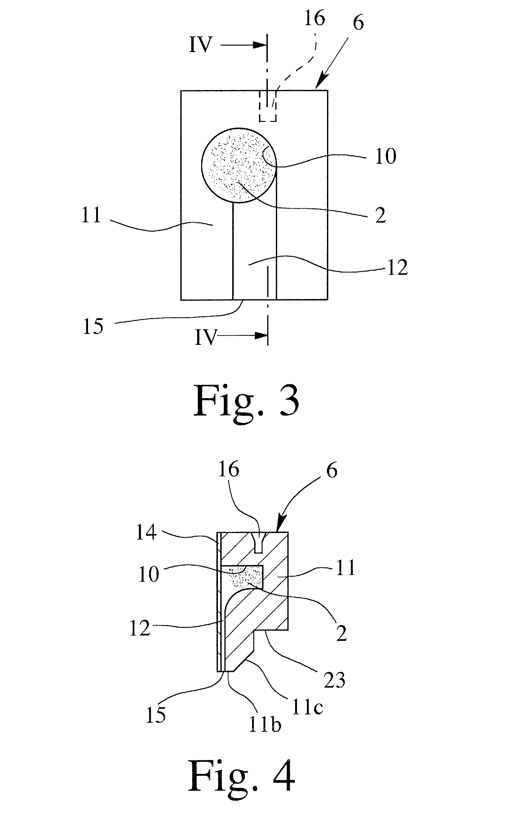
[0051]The dispensing device 1 may be used for dispensing any formulation 2 as defined in the introductory part of the description. In particular, a medical formulation 2 or a formulation 2 for inhalation will be used. The formulation 2 preferably contains or consists of at l...


PUM


Abstract

A dispensing device has a storage device and an air pump for dispensing a medical formulation has multiple inserts, each insert containing a single dose of the formulation. Each insert is located in a separate sealed cavity. The cavities can be individually opened for dispensing the respective dose from the respective insert. A connecting element that is moveable relative to the cavities is provided for individually opening and supplying pressurized gas thereto for dispensing a respective dose of formulation, and the storage device has an empty, hollow or dummy receptacle into which the connecting element is engaged in a state prior to first use of the dispensing device.

Description

BACKGROUND OF THE INVENTION[0001]1. Field of Invention[0002]The present invention relates to a dispensing device for dispensing a preferably medical formulation, in particular containing or consisting of a drug or mixture of drugs.[0003]2. Description of Related Art[0004]Drugs delivered through dispensing devices, in particular inhalers, are intended to optimally target specific sites in the pulmonary system. These sites include the nasal passages, the throat, and various locations within the lungs, such as the bronchi, bronchioles and alveolar regions. The ability to deliver drugs to a target area depends inter alia on the aerodynamic sizes of the particles or droplets. As currently believed to be understood, particles having an aerodynamic diameter of less than 2 micrometer are considered to be potentially optimal for deposition in the alveolar region of the lung. Particles that have an aerodynamic diameter of between 2 and approximately 5 micrometer may be more suitable for deliv...

Claims


Application Information

Patent Timeline
Patent Type & Authority Applications(United States)
IPC IPC(8): A61M15/00B67D5/60B65D83/00B67D7/78
CPCA61M15/0045A61M2016/0039A61M2202/064A61M2205/07A61M2205/8225A61M2205/8293A61M15/0008A61M15/0031A61M15/0036A61M15/0041A61M15/0048A61M15/0061A61M15/0075A61M11/001
Inventor ROHRSCHNEIDER, MARCBESSELER, JENSVON BRUNN, TIMOREINHOLD, THOMAS SOWDEN
Owner BOEHRINGER INGELHEIM INT GMBH
Why Eureka
Try Eureka