Water retention/detention system

a water retention and detention system technology, applied in mechanical equipment, branching pipes, transportation and packaging, etc., can solve the problems of difficult connection of corrugated pipes to corrugated tanks, labour intensive and time-consuming installation, and relatively complex corrugated surfaces

Inactive Publication Date: 2008-12-04
BLUESCOPE STEEL LTD
View PDF4 Cites 1 Cited by
  • Summary
  • Abstract
  • Description
  • Claims
  • Application Information

AI Technical Summary

Benefits of technology

[0043]Moreover, the pipes of one or more water retention or detention systems embodied

Problems solved by technology

The problem with this traditional stormwater detention system is that its installation is labour intensive and time consuming.
The corrugated pipes are connected to the tank via joining systems which, by nature of the corrugated surfaces to be joined, are relatively complex.
This known detention system suffers from one

Method used


Image

  • Water retention/detention system
  • Water retention/detention system
  • Water retention/detention system

Examples


Embodiment Construction

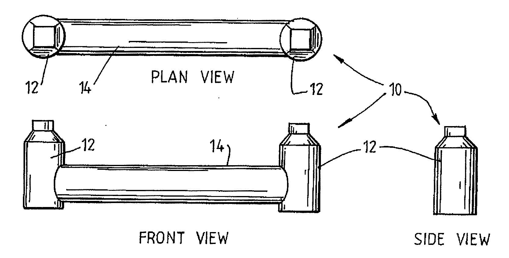
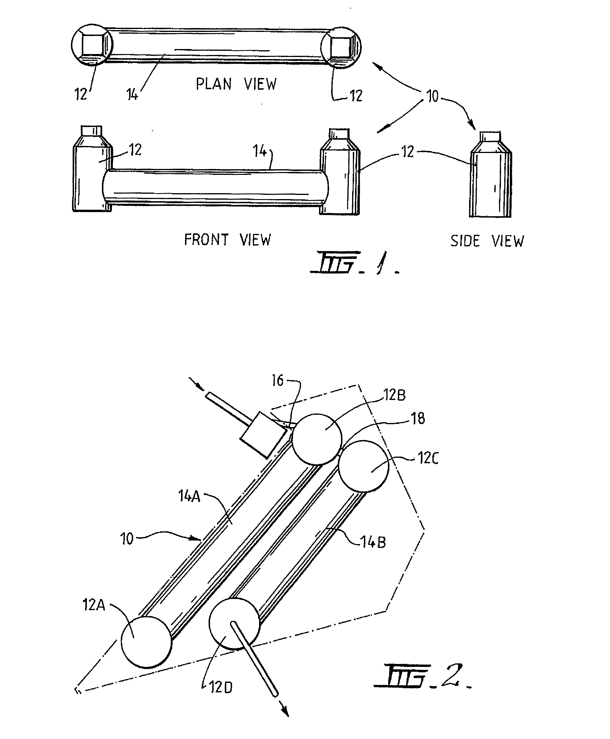
[0058]FIGS. 1 and 2 show water retention and detention systems in the form of stormwater detention and rainwater retention systems, respectively, designated generally by the numeral 10. In each of these embodiments, the retention or detention system 10 comprises one or more water storage tanks identified by the numerals 12, in FIG. 1 and by the numerals 12A / B / C in FIG. 2 connected to one or more pipes identified by the numeral 14 in FIG. 1 and by the numerals 14A / B in FIG. 2. The tanks and the pipes 14 are generally positioned underground, and the number of the tanks and their interconnection via the pipes is dependent on the particular application and site constraints.

[0059]In the stormwater detention system 10 of FIG. 1, there are two storage tanks 12 that are interconnected by one pipe 14. At least one of the tanks provides a controlled flow of stormwater to a stormwater catchment pit or system through a discharge overflow or from a small outlet portal (not shown) provided in a l...


PUM


Abstract

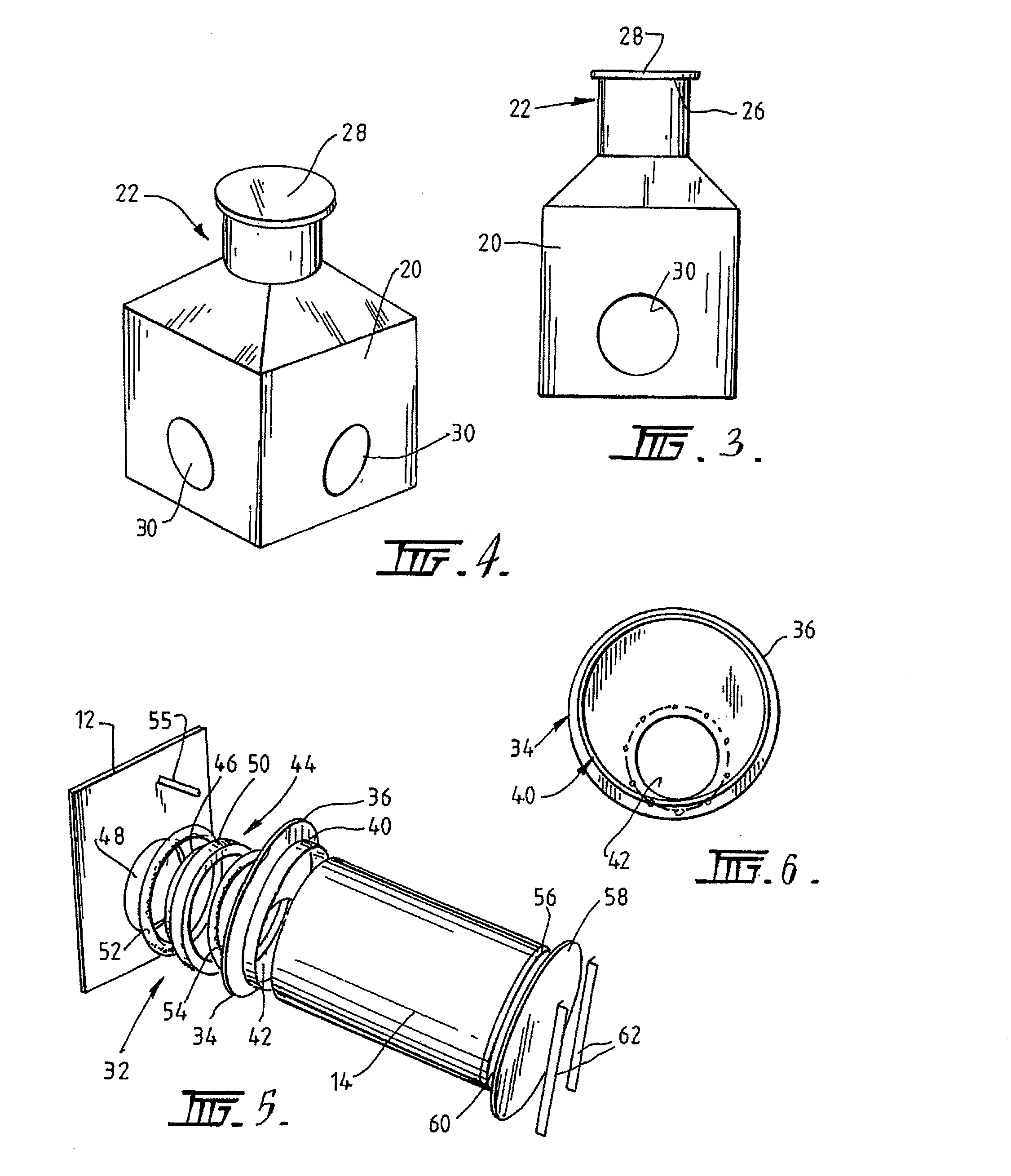
An underground water retention or detention system for collecting stormwater, rainwater, sewerage, effluent or other waters, and controlled release of the water is disclosed. Typically, the tanks are formed from a plastics or polymeric material such as high density polyethylene. The pipes may be polymer coated corrugated steel pipes. Tanks suitable for use in the water retention and detention systems are also described together with connection fittings for connection of pipes to the tanks. Generally, the connection fittings are adapted to provide structural support to perimeter walls of the tanks about respective openings formed in the tank for the connection of the pipes.

Description

FIELD OF THE INVENTION[0001]The present invention broadly relates to a water retention or detention system and particularly, though not exclusively, to a stormwater retention or detention system. The invention further relates to storage tanks and connection fittings adapted for use in the water retention or detention system.BACKGROUND OF THE INVENTION[0002]For both residential and commercial sites there is a requirement to provide adequate stormwater detention and water retention.[0003]A typical stormwater detention system includes a soakwell which is plumbed to plastic conduits connected to major contributors of stormwater runoff, such as drains and roofing downpipes. The soakwell is buried below ground and is designed to collect large volumes of rainwater and allow for its gradual seepage into sand or aggregate within the soakwell. The soakwell may be constructed in-situ from interlocking concrete blocks or alternatively may be in the form of a tank. The problem with this traditio...

Claims


Application Information

Patent Timeline
IPC IPC(8): F16L41/08F16L23/00
CPCE03F5/101Y10T137/85938Y02A10/30
Inventor FABER, ROBERT HENRY GREYWALLACE, NEIL EDWIN
Owner BLUESCOPE STEEL LTD
Why Eureka
Try Eureka