Method For Manufacturing a Post Insulator and a Post Insulator

a post insulator and manufacturing method technology, applied in the field of post insulator manufacturing, can solve the problems of difficult to fill the entire inner volume of the tube, short circuit risk, and cracks in the core, and achieve the effect of reducing the risk of short circui

Inactive Publication Date: 2008-12-04
ABB TECH AG
View PDF6 Cites 5 Cited by
  • Summary
  • Abstract
  • Description
  • Claims
  • Application Information

AI Technical Summary

Benefits of technology

[0009]The object of the present invention is to provide a method for manufacturing a post insulator of the type described above as well as a post insulator reducing the risks of shortcircuits.

Problems solved by technology

However, in post insulators of this type already known there is a not negligible risk of occurrence of shortcircuits through the post insulator as a consequence of damp penetrating into the interior of the post.
The reason for this is that it is difficult to fill the entire inner volume of the tube by said core and keep the total filling over the time.
Furthermore, cracks may also be created in the core.
Thus, damp may be introduced into spaces formed between the core and the tube and inside the core and cause a shortcircuit through the post insulator.

Method used


Image

  • Method For Manufacturing a Post Insulator and a Post Insulator
  • Method For Manufacturing a Post Insulator and a Post Insulator

Examples


Embodiment Construction

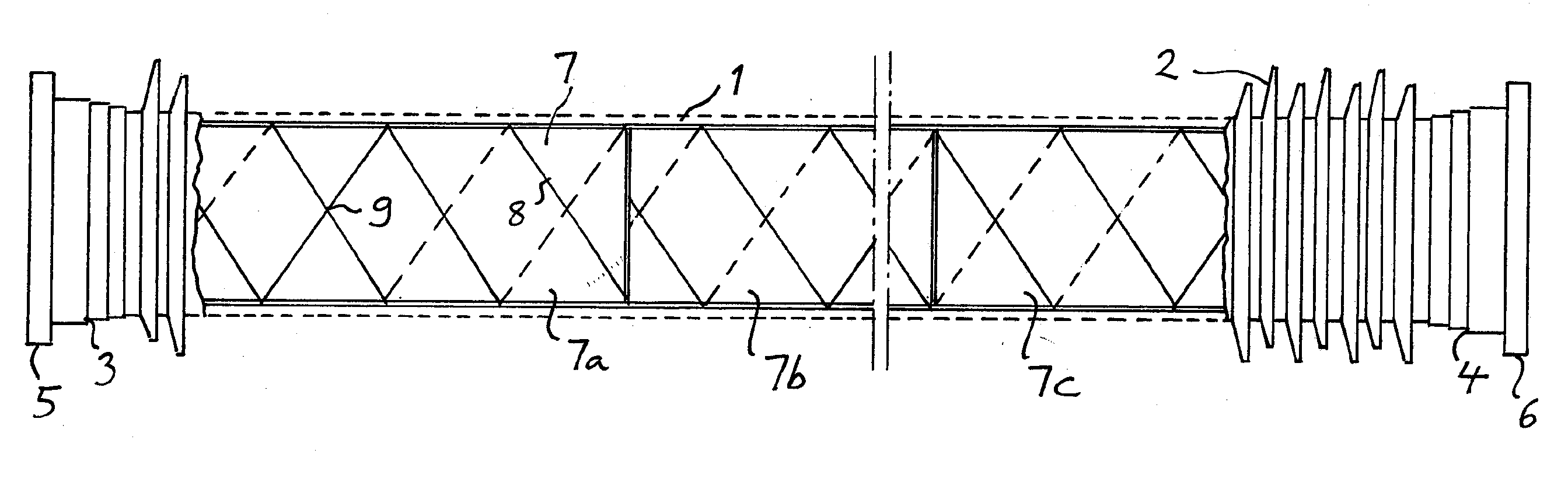
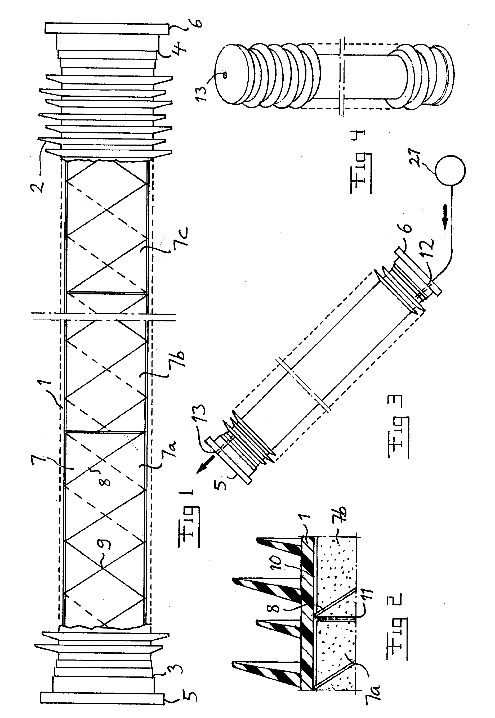
[0037]FIG. 1 shows schematically a post insulator according to the present invention. This is made of a tube 1 of a fibre composite, such as glass fibre epoxy, which here has a length of approximately six metres and an inner diameter of 31 cm and an outer diameter of 33 cm. The tube 1 has an outer profile of rings 2 of silicon rubber. The tube is at each end thereof provided with flanges 3, 4 of aluminium adhesived to the ends of the tube. Each end of the tube is provided with a flange cover 5, 6 having an outer diameter of about 46 cm and enclosing the inner volume of the tube.

[0038]The inner volume of the tube is occupied by a core 7 of an insulating material, such as foamed plastic.

[0039]The further structure of the post insulator will now be described while simultaneously describing the method for manufacturing the post insulator and making reference to all the figures. In this manufacturing process one of the flange covers, such as the flange cover 6, is initially not in place ...


PUM

PropertyMeasurementUnit
angleaaaaaaaaaa
angleaaaaaaaaaa
voltagesaaaaaaaaaa

Abstract

A method for manufacturing a post insulator. A core is introduced into a tube of an insulating stiff material while leaving a small circumferential space separating the core and inner walls of the tube. Adhesive is introduced under an overpressure into an interior of the tube and is cured while maintaining an overpressure in the interior of the tube.

Description

TECHNICAL FIELD OF THE INVENTION AND PRIOR ART[0001]The present invention relates to a method for manufacturing a post insulator.[0002]The invention relates to such post insulators of any size used for separating two electrical potentials, normally a high electrical potential from ground. They may be used as so called station post insulators in switchgears in converter stations of plants for transmitting electric power, such as for separating valves in a converter in a station of a HVDC (High Voltage Direct Current) plant with respect to ground. Another possible use is for carry overhead electrical high voltage cables.[0003]Typical sizes for such a post insulator are lengths, i.e. heights, of 6-8 m and diameters of 25-40 cm, but any other size is possible.[0004]The voltage, i.e. potential difference, in question may for instance be 800 kV, although quite different voltages are possible. The voltage may be an alternating voltage or a direct voltage.[0005]The invention relates to such...

Claims


Application Information

Patent Timeline
Patent Type & Authority Applications(United States)
IPC IPC(8): B65B7/28H01B17/00
CPCH01B13/147Y10T29/49995H01B19/04H01B17/325
Inventor PETTERSSON, JOAKIMLUNDQUIST, MATTIAS
Owner ABB TECH AG
Why Eureka
Try Eureka