Brake Shoe for Elevator Emergency Stop

a technology for elevators and brake shoes, applied in elevators, transportation and packaging, etc., can solve the problems of complex fastening with the shoe, the danger of the shoe being split from the bottom of the groove, and the material cost of ceramics is over ten times that of cast iron, so as to prevent thermal stress acting, prevent bending stress, and prevent cracking

Inactive Publication Date: 2008-12-04
HITACHI LTD
View PDF10 Cites 18 Cited by
  • Summary
  • Abstract
  • Description
  • Claims
  • Application Information

AI Technical Summary

Benefits of technology

[0011]According to the present invention, the shoe is made of a cast iron material and the grooves whose depth is 3 mm or more and not exceeding 1.7 times the width of the gear teeth are formed, and it is thereby possible to prevent thermal stress acting on the groove bottom from exceeding a yield point of the shoe material and also prevent bending stress at the groove bottom from exceeding tensile strength. Therefore, even when a cast iron material is used, it is possible to prevent cracking in a high temperature environment in which the temperature of the sliding surface of the shoe is higher than 1000° C. and reliably stop the cage in the event of an emergency, thus providing high reliability.

Problems solved by technology

As a result of increasing amount of heat generated on the sliding surface caused by increases in speed and capacity, conventional techniques using cast iron involve a danger that the shoe may be split from the bottom of the grooves on which stress is concentrated because of thermal stress acting on the vicinity of the sliding surface.
Furthermore, the use of a ceramic friction material having excellent hest resistance for the shoe can secure the strength of the friction material, but the material cost of ceramics is over ten times that of cast iron and the structure of fastening with the shoe is complicated, leading to drive up the cost of the entire apparatus.
Furthermore, since ceramics is a brittle material, compared to the cast iron material, securing predetermined quality thereof requires stringent process management and requires extreme caution during machining and assembly.

Method used


Image

  • Brake Shoe for Elevator Emergency Stop
  • Brake Shoe for Elevator Emergency Stop
  • Brake Shoe for Elevator Emergency Stop

Examples


Embodiment Construction

[0023]Hereinafter, a brake shoe for elevator emergency stop will be explained with reference to the attached drawings.

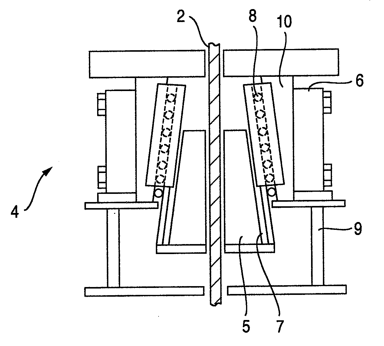
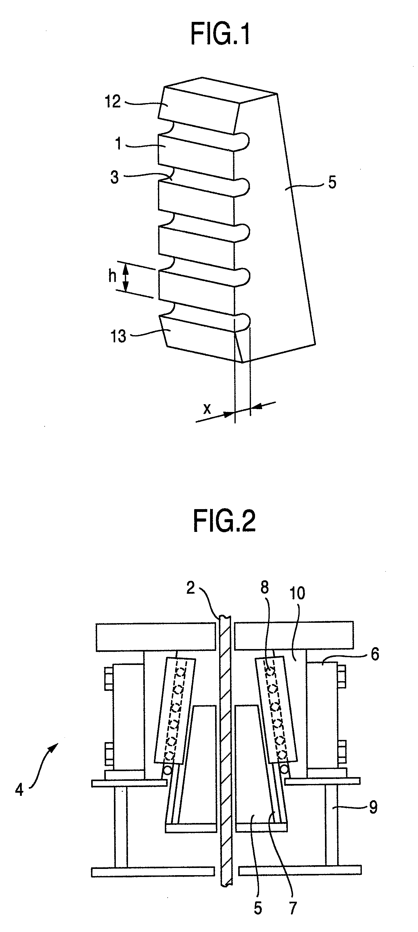
[0024]FIG. 2 is a longitudinal cross-sectional view of a safety gear and a safety gear 4 is configured to be symmetric with respect to a guide rail 2. The safety gear has a pair of shoes 5 formed so as to have a trapezoidal cross section, a top side of the brake shoe 5 corresponds to a short side and a bottom side corresponds to a long side.

[0025]The pair of brake shoes 5 is arranged substantially parallel to the guide rail 2 with a small distance therefrom to sandwich the guide rail 2. The back surface of the brake shoe 5 forms a wedge-like smooth slope which narrows toward the top.

[0026]Furthermore, a guide plate 8 for guiding the brake shoe 5 is provided for a guide member 10 so as to move the brake shoe 5 to a predetermined position. The inside of the guide member 10 forms a slope parallel to the slope of the brake shoe 5 and the outside thereof forms a vertical ...


PUM


Abstract

The present invention prevents cracking of a brake shoe even when the sliding surface of the brake shoe is heated to a high temperature and provides high reliability. The present invention provides a brake shoe for elevator emergency stop which generates a braking force by pressing brake shoes against a guide rail and making the brake shoes 5 slide to stop an elevator cage in the event of anomalies, including the brake shoes made of a cast iron material having a plurality of grooves 3 formed in a direction substantially perpendicular to the guide rail and gear teeth which constitute a sliding surface with the brake shoes 5 formed as gaps between the grooves, wherein the depth of the grooves is 3 mm or more and not more than 1.7 times the width of the gear teeth.

Description

BACKGROUND OF THE INVENTION[0001]The present invention relates a brake shoe for elevator emergency stop for and is particularly suitable as a brake shoe operated when the elevator speed reaches or exceeds a predetermined speed.[0002]It is obligatory to provide an elevator with a safety gear, that is, a brake shoe for elevator emergency stop to stop a cage at appropriate deceleration when the cage descends at a predetermined or higher speed.[0003]The safety gear uses a shoe with two trapezoidal friction members arranged inside surrounded by an elastic body and presses an elevator guide rail set on the wall of a hoist way with the two shoes when the cage reaches the predetermined or higher speed. The safety gear then generates a braking force using a force originating from elastic deformation of the elastic body and the shoe is conventionally formed of a cast iron material having an appropriate coefficient of friction and wear resistance in many cases.[0004]The safety gear using a cas...

Claims


Application Information

Patent Timeline
Patent Type & Authority Applications(United States)
IPC IPC(8): B66B5/16
CPCB66B5/22
Inventor SATO, GOROSAWADA, TAKAHIKONAKAYAMA, MASATOTERAMOTO, TAKASHIMIYATA, KOICHIOMORI, MITSUGUZAMA, HIDETAKAGOTOH, TOSHIHIKO
Owner HITACHI LTD
Why Eureka
Try Eureka