Method for manufacturing electroluminescence element and evaporation mask

a technology of electroluminescence element and evaporation mask, which is applied in the direction of electroluminescent light sources, vacuum evaporation coatings, coatings, etc., can solve the problems of inability to achieve sufficient patterning precision in the evaporation layer, and the possibility of employing a method

Inactive Publication Date: 2003-03-06
SANYO ELECTRIC CO LTD
View PDF8 Cites 16 Cited by
  • Summary
  • Abstract
  • Description
  • Claims
  • Application Information

AI Technical Summary

Benefits of technology

[0015] According to yet another aspect of the present invention, the material for the evaporation mask has a thermal endurance which is at least approximately 50.degree. C. higher than the thermal endurance of the plastic substrate.
[0016] As described, by using, as the material for the evaporation mask, a material whose thermal expansion coefficient is similar to that of the plastic used as the material for the plastic substrate of the element, it is possible to create a situation wherein the thermal deformation of the evaporation mask is similar to the thermal deformation of the plastic substrate when heated by the evaporation source. Therefore, the thermal deformation of the evaporation mask can be substantially cancelled and an evaporation layer can be precisely patterned on the plastic substrate.
[0018] According to another aspect of the present invention, it is preferable that in the method for manufacturing, each of the materials for the evaporation mask and for the mask holding section has a thermal endurance which is at least approximately 50.degree. C. higher than the thermal endurance of the plastic substrate. By using a material having a thermal endurance which is at least 50.degree. C. higher than the thermal endurance of the plastic substrate, it is possible to achieve sufficient durability for the evaporation mask and the mask holding section which are placed closer to the evaporation source than the plastic substrate.
[0020] In this manner, by using a material, for the mask holding section, having a thermal expansion coefficient similar to the plastic substrate, that is, a thermal expansion coefficient similar also to the evaporation mask, it is possible to inhibit the thermal stress between the holding section and the evaporation mask even when the temperature of the holding section is increased during evaporation, and to prevent application of excessive stress to the evaporation mask.

Problems solved by technology

For example, because a material for an organic layer used in an organic EL element is vulnerable to moisture, it is not possible to employ a method, for example, in which an organic layer is first formed on the entire surface of the substrate and then the organic layer is etched and patterned into a predetermined shape.
However, there had been a problem in that sufficient patterning precision cannot be achieved in the evaporation layer evaporated using the nickel mask.

Method used


Image

  • Method for manufacturing electroluminescence element and evaporation mask
  • Method for manufacturing electroluminescence element and evaporation mask
  • Method for manufacturing electroluminescence element and evaporation mask

Examples


Embodiment Construction

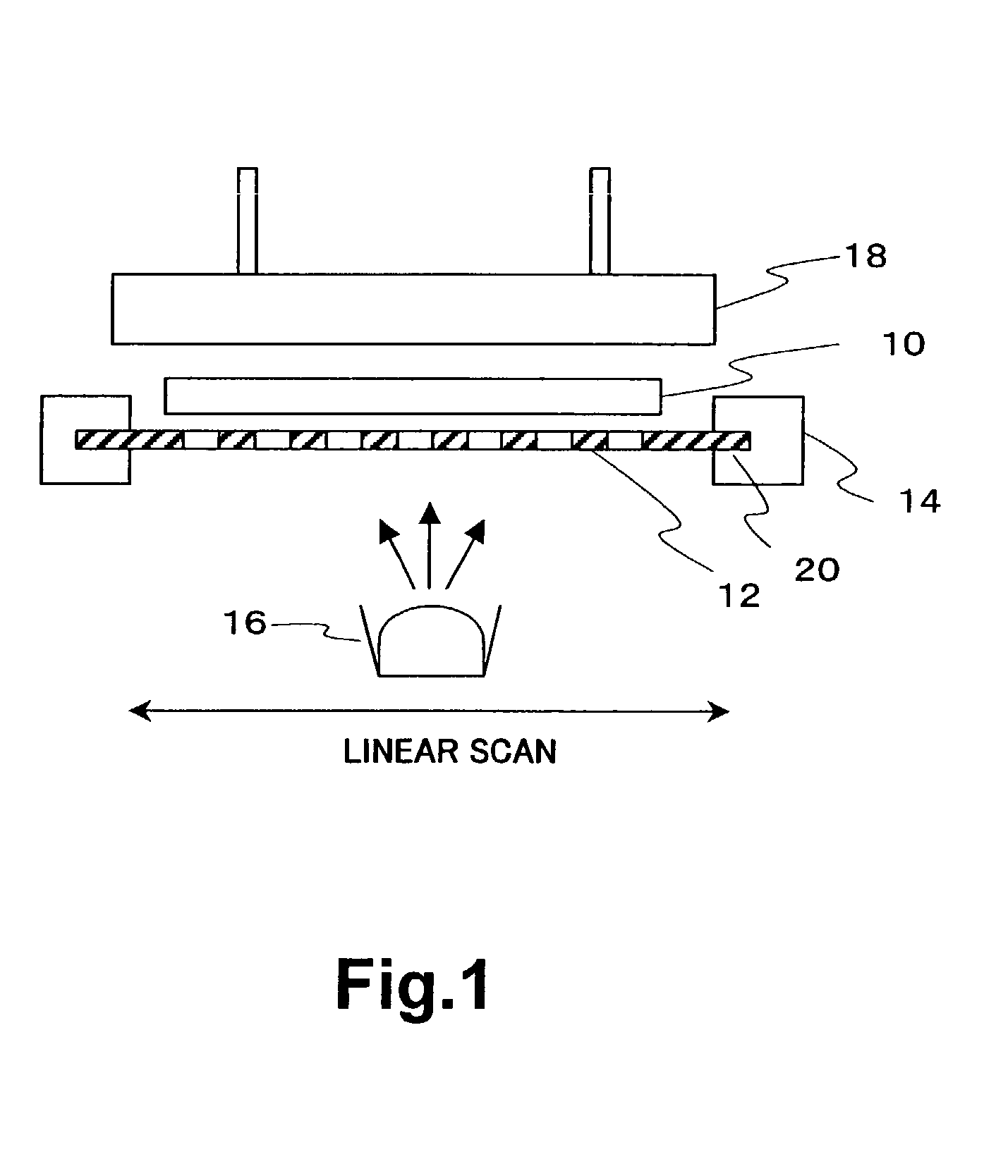
[0024] A preferred embodiment of the present invention will now be described referring to the drawings. FIG. 1 is a diagram for explaining an example method for manufacturing according to a preferred embodiment.

[0025] An evaporation mask 12 is placed below a plastic substrate 10 for forming a portion of an EL panel, the evaporation mask 12 having an overall size greater than that of the plastic substrate 10. Although in FIG. 1, the plastic substrate 10 and the evaporation mask 12 are shown separated from each other, in practice the plastic substrate 10 and the evaporation mask 12 are in contact with each other over almost their entire surface. The ends of the mask 12 are supported by a supporting mechanism 14.

[0026] Below the evaporation mask 12, an evaporation source 16 is placed for heating an evaporation material to a temperature of, for example, approximately 300.degree. C. In this example, the evaporation source 16 is moveable in the right and left direction of the page and int...


PUM

PropertyMeasurementUnit
temperatureaaaaaaaaaa

Abstract

An evaporation mask is placed between an evaporation source and a plastic substrate. An evaporation substance from the evaporation source is allowed to selectively pass through one or more openings formed on the evaporation mask corresponding to the pattern of an evaporation layer of an EL element, to form the evaporation layer on the plastic substrate. As the material for the evaporation mask, a material whose thermal expansion coefficient is similar to (for example, within a range of ±30% of) the thermal expansion coefficient of the plastic substrate, for example, a plastic material such as a polyimide, is employed. It is preferable to employ a material having a thermal endurance which is, for example, at least approximately 50° C. higher than the thermal endurance of the plastic substrate. By employing such a material for the evaporation mask, it is possible to ensure that the plastic substrate and the evaporation mask will exhibit the same degree of thermal deformation during evaporation, thereby enabling improvement in the precision of evaporation patterning.

Description

[0001] 1. Field of the Invention[0002] The present invention relates to a method for manufacturing an EL element formed on a plastic substrate.[0003] 2. Description of the Related Art[0004] A type of EL display panel is known in which an organic EL element or the like is employed as an emissive element in each pixel. Expanding use of such an EL display panel as a self-illuminating flat panel is widely expected.[0005] As an organic EL element, a structure is known, for example, in which an anode made of a transparent electrode such as ITO (Indium Tin Oxide) and a cathode made of a metal electrode such as Al or a magnesium alloy are layered on a glass substrate, with an organic layer including an emissive layer provided between the anode and cathode.[0006] For manufacturing such an organic EL element, an evaporation method is employed for forming the organic layer and the metal electrode. During the evaporation, an evaporation mask is used onto which openings are formed corresponding ...

Claims


Application Information

Patent Timeline
Patent Type & Authority Applications(United States)
IPC IPC(8): C23C14/04H01L27/32H01L51/40H05B33/10H01L51/56
CPCC23C14/044H01L27/3211H01L51/001H01L51/56H10K59/35H10K71/164H10K71/00H05B33/10
Inventor NISHIKAWA, RYUJIYAMADA, TSUTOMU
Owner SANYO ELECTRIC CO LTD
Why Eureka
Try Eureka