Built-in missile radar calibration verification

a radar calibration and missile technology, applied in the field of array antenna calibration system and methods for imaging array antennas, can solve the problems of unsuitable conventional techniques, unsuitable real-time calibration verification of deployed, in-service radar imaging applications, and unacceptable global supply chain management of volume products

Inactive Publication Date: 2008-12-04
THE BOEING CO
View PDF4 Cites 21 Cited by
  • Summary
  • Abstract
  • Description
  • Claims
  • Application Information

AI Technical Summary

Benefits of technology

[0004]In accordance with embodiments of the present invention, a RADAR calibration verification apparatus and method for a phased array antenna may include a responder selected from an array element of the array antenna; an interrogation signal having a phase angle; an interrogator coupled with the responder by the interrogation signal; and a verification processor coupled to the responder and the interrogator. The verification processor causes the interrogation signal to be coupled with the responder and the interrogator and is adapted to determine a responder characteristic interrogation response to the interrogation signal. The verification processor then can cause the phase angle of the interrogation signal to be rotated by about 180 degrees in phase, thereby generating a conjugate signal, which couples with the responder and the interrogator. The verification processor then can determine a responder characteristic conjugate response to the conjugate signal which, when combined with the characteristic interrogation response produces a responder difference characteristic representative of a present calibration verification state of the array antenna. A memory can store a previous calibration verification state of the array antenna or data representative thereof. The present calibration verification state is compared to the previous calibration verificatio

Problems solved by technology

High-resolution applications tend to pose a demanding calibration challenge.
However, techniques that may be suitable in a laboratory or other deliberative setting, or designed for large, one-of-a-kind installations, may be unacceptably cumbersome for volume products managed in a global s

Method used


Image

  • Built-in missile radar calibration verification
  • Built-in missile radar calibration verification
  • Built-in missile radar calibration verification

Examples


Embodiment Construction

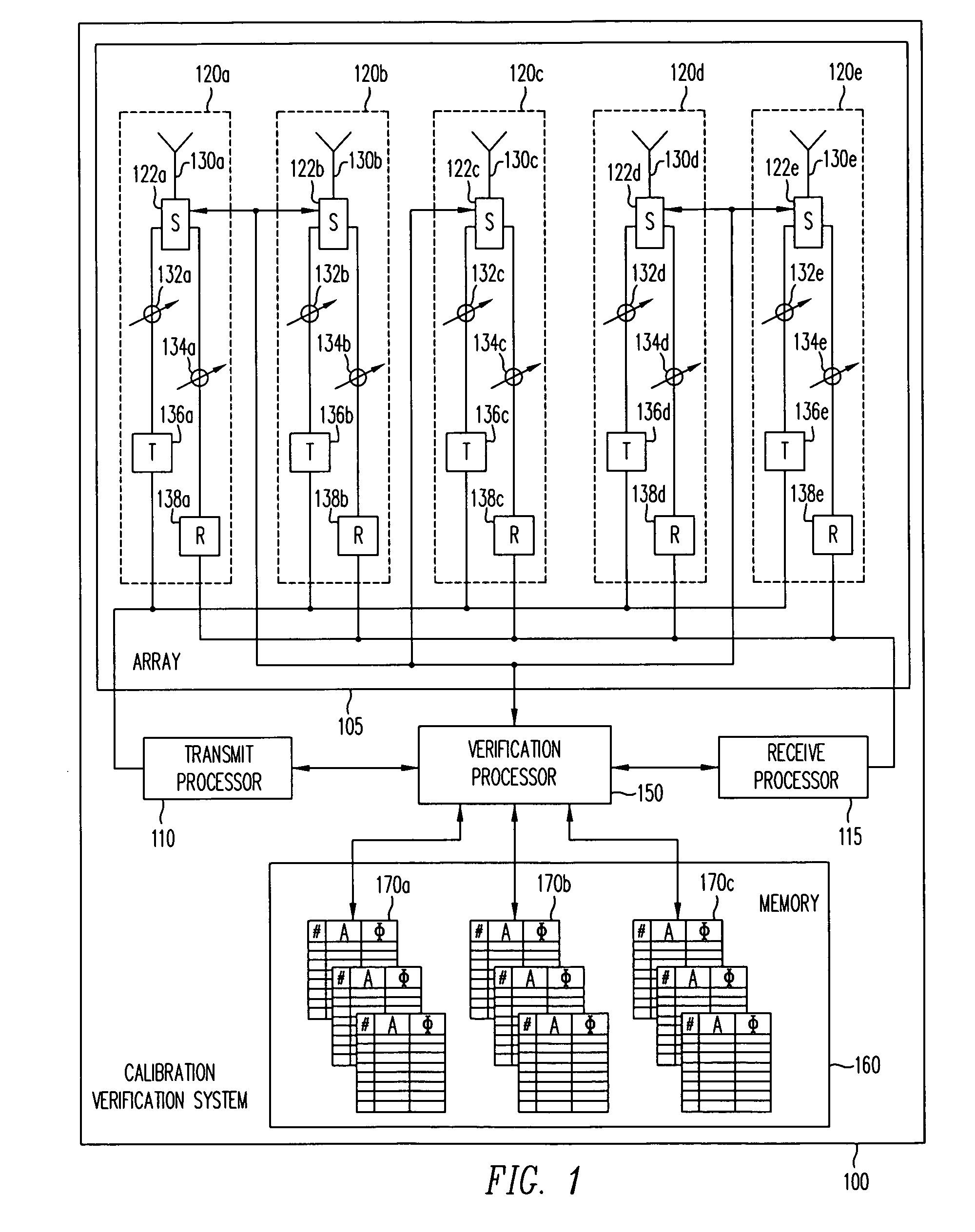
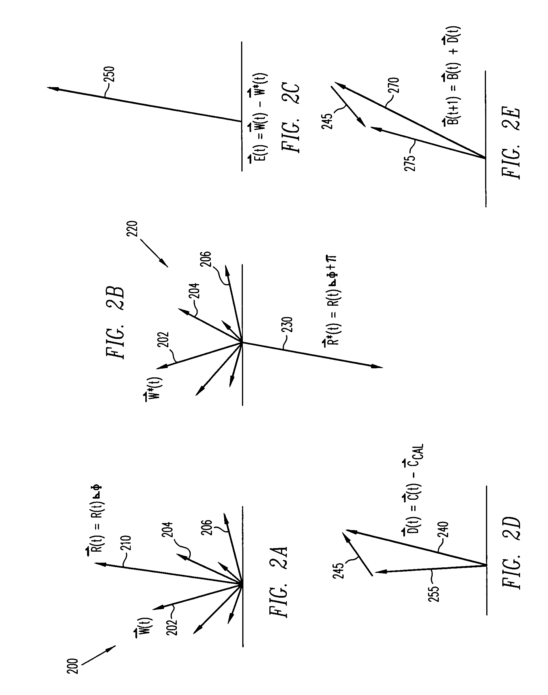
[0016]Embodiments of the present invention provide apparatus and methods for rapidly verifying a present calibration verification state of an array antenna, relative to a previous calibration verification state. In general, these apparatus and methods can be built-in to the phased array system, as it is disposed in its application platform. In addition to verifying the present calibration verification state of an array antenna, certain inventive embodiments herein are suitable for testing high-resolution phased-array imaging applications prior to entering service, after deployment, and even while in use. In selected embodiments, a verification processor may verify the present calibration verification state of an array antenna, by selecting a mode, an interrogator, and a responder; by coupling an interrogation signal with the interrogator and the responder; by determining a characteristic interrogation response of the responder to the interrogation signal; by commanding a conjugate r...


PUM


Abstract

Array antenna calibration verification coupling interrogator and responder with mode-related interrogation signal having a previous calibration phase angle, producing in responder a characteristic interrogation response. Conjugate signal is generated by reversing phase of interrogation signal, producing in responder a characteristic conjugate response. Interrogation and conjugate responses sensed and combined to determine difference characteristic for responder array element. Responder difference characteristic iteratively determined for elements in antenna array representative of present calibration verification state. Present and previous calibration verification states compared, with significant variation adapting array to desired calibration verification state. Verification processor controls interrogator, responders, and signals providing built-in missile RADAR calibration verification.

Description

TECHNICAL FIELD[0001]The present invention relates generally to array antennas, and more particularly, for example, to calibration systems and methods for imaging array antennas.RELATED ART[0002]Acceptable performance of a phased array antenna is typically achieved by employing suitable calibration techniques to mitigate the non-uniformities in the patterns of the radiating elements. High-resolution applications tend to pose a demanding calibration challenge. Some techniques employ sum-and-difference characterization. Other calibration techniques employ complex analysis of constructive and destructive interferences emanating and detected by a phased array as a whole, or in successive parts. Still others determine both near-field and far-field metrics, which are then used to adjust the antenna pattern. Most techniques employ test or signal equipment external to the array antenna or its application platform. However, techniques that may be suitable in a laboratory or other deliberativ...

Claims


Application Information

Patent Timeline
IPC IPC(8): G01S7/40
CPCG01S7/024G01S7/4004G01S2013/0254H01Q3/267
Inventor WOOLDRIDGE, JOHN J.
Owner THE BOEING CO
Why Eureka
Try Eureka