Reflection characteristic measuring apparatus, and method for calibrating reflection characteristic measuring apparatus

a technology of reflection characteristic and measuring apparatus, which is applied in the direction of optical radiation measurement, instruments, spectrometry/spectrophotometry/monochromators, etc., can solve the problem of long measurement time and other problems

Active Publication Date: 2008-12-04
KONICA MINOLTA SENSING INC
View PDF1 Cites 50 Cited by
  • Summary
  • Abstract
  • Description
  • Claims
  • Application Information

AI Technical Summary

Benefits of technology

[0010]In a reflection characteristic measuring apparatus and a method for calibrating the reflection characteristic measuring apparatus, multiple standard spectral characteristics, or multiple calibration data based on the multiple standard spectral characteristics are respectively obtained in advance with corresponding reference values relating to an emission characteristic of a light source. An optimum standard spectral characteristic or an optimum calibration data is selected from the multiple standard spectral characteristics or the multiple calibration data. A spectral reflection characteristic of a sample is calculated using the selected standard spectral characteristic or the selected calibration data. Accordingly, the inventive reflection characteristic measuring apparatus and the inventive method for calibrating the reflection characteristic measuring apparatus are advantageous in correcting an influence of a change in spectral intensity of illumination light, without using a reference spectral section or an equivalent element.

Problems solved by technology

On the other hand, if a reflection characteristic measuring apparatus is designed in such a manner that the apparatus is required to wait until the emission intensity is transited to a normal state, in other words, until the driving condition of the incandescent lamp is stabilized, to secure precision, a long measurement time may be required.

Method used


Image

  • Reflection characteristic measuring apparatus, and method for calibrating reflection characteristic measuring apparatus
  • Reflection characteristic measuring apparatus, and method for calibrating reflection characteristic measuring apparatus
  • Reflection characteristic measuring apparatus, and method for calibrating reflection characteristic measuring apparatus

Examples


first embodiment

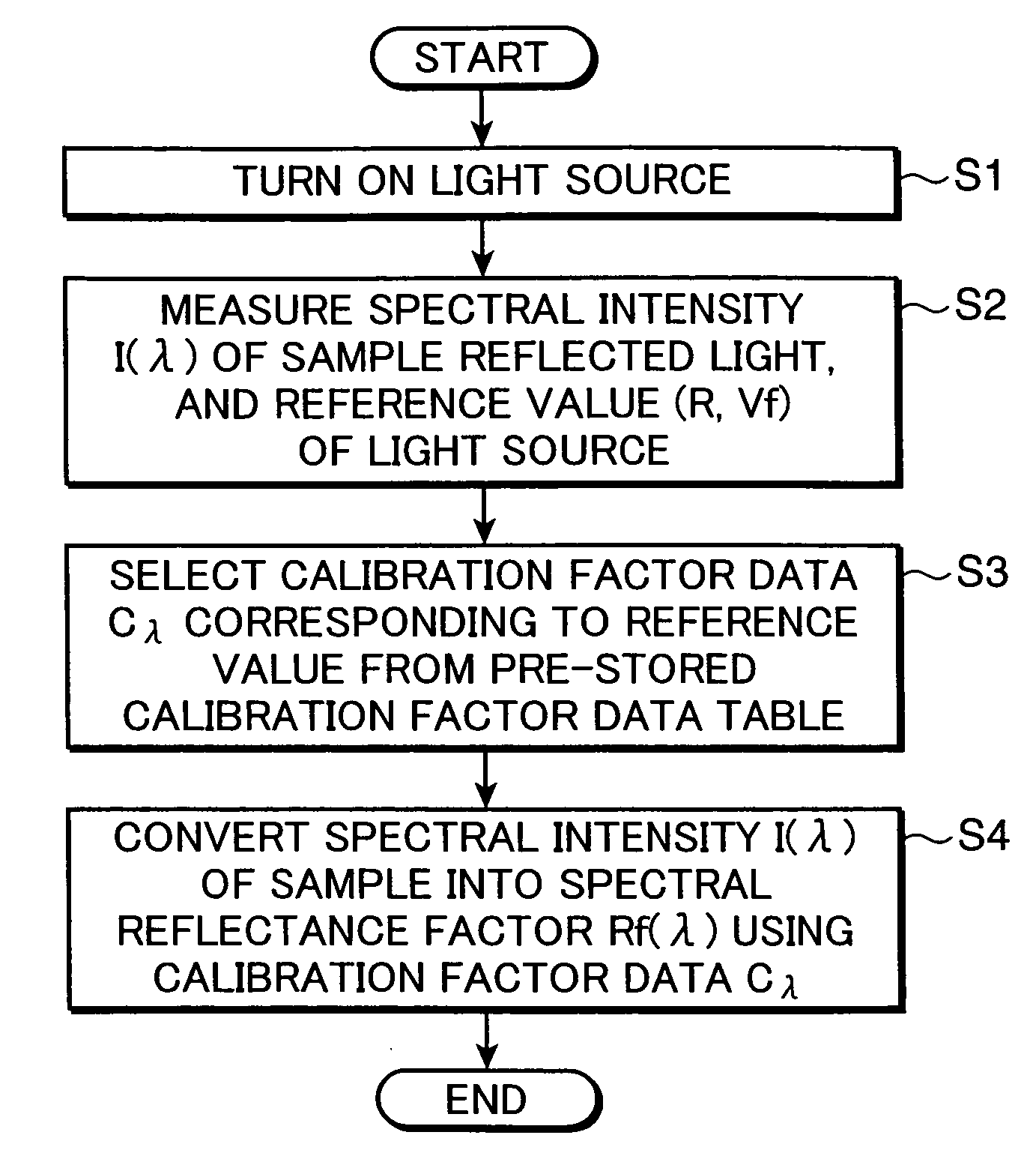
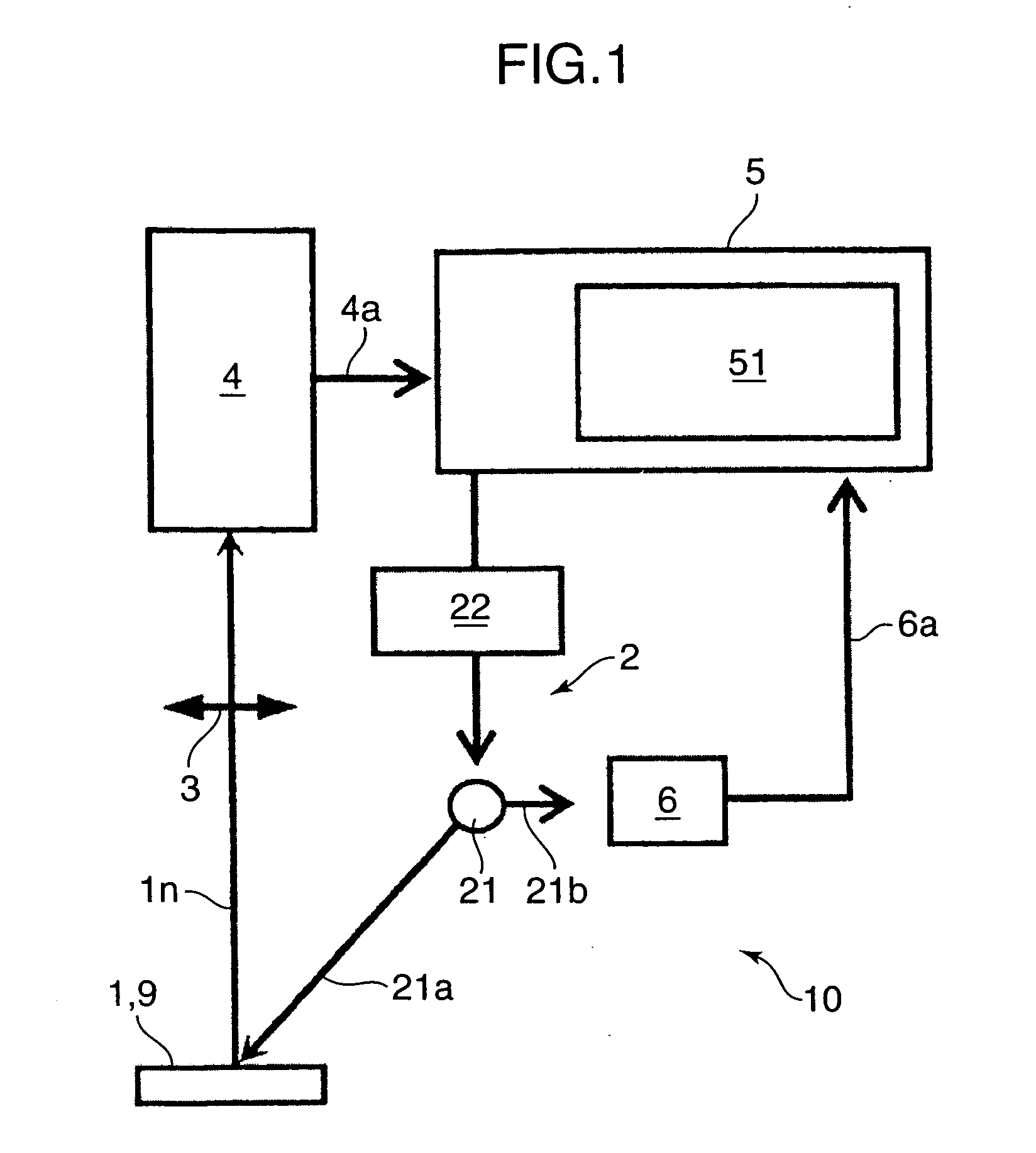
[0024]FIG. 1 is a diagram showing an example of an arrangement of a reflection characteristic measuring apparatus in accordance with the first embodiment of the invention. Referring to FIG. 1, the reflection characteristic measuring apparatus 10 includes an illuminator 2, an objective lens 3, a spectral device 4, a computation control device 5, and a light sensor 6.

[0025]The illuminator 2 is adapted to illuminate a sample 1. The illuminator 2 includes e.g. an incandescent lamp 21 as a light source, and a driving circuit 22 for driving the incandescent lamp 21 to turn on the incandescent lamp 21. In this embodiment, the driving circuit 22 is driven at a constant voltage to turn on the incandescent lamp 21.

[0026]The objective lens 3 is an optical lens or a lens group, which is operable to receive a normal direction component in, indicating a light component in a direction of normal to a sample surface, in sample reflected light reflected on the sample 1, which is illuminated with ligh...

second embodiment

[0041]FIG. 4 is a diagram showing an example of an arrangement of a reflection characteristic measuring apparatus 10a in accordance with the second embodiment of the invention. The reflection characteristic measuring apparatus 10a includes an illuminator 2a incorporated with a white light emitting diode (hereinafter, called as a “white LED”) 23, as a light source, in place of the incandescent lamp 21, as an incandescent light source, in the reflection characteristic measuring apparatus 10. In this embodiment, a sample is illuminated with a light flux 23a from the white LED 23 which is driven by a driving circuit 24 at a constant current. A spectral intensity distribution of the white LED 23 primarily depends on a temperature of an LED element i.e. an element temperature. As shown in FIG. 6, there is a relation between a forward voltage Vf of the white LED 23 driven at a constant current (in this embodiment, the constant current is about 20 mA), and the element temperature, depending...

third embodiment

[0047]The reflection characteristic measuring apparatus 10a in the second embodiment includes the illuminator 2a incorporated with the single white LED 23 as a light source. As shown in FIG. 7, a reflection characteristic measuring apparatus 10b in accordance with the third embodiment of the invention includes an illuminator 2b incorporated with two LEDs, as a light source, wherein the two LEDs have spectral intensity distributions different from each other. The two LEDs are, as shown in FIG. 8, for instance, an LED 25 (hereinafter, called as the “white LED 25”) having a spectral intensity distribution corresponding to blue light emission, and yellow fluorescent emission excited by the blue light emission; and an LED 27 (hereinafter, called as the “violet LED 27”) having a spectral intensity in a wavelength band where the white LED 25 hardly has a spectral intensity, e.g. a wavelength band from 400 to 450 nm.

[0048]The white LED 25 and the violet LED 27 are respectively driven by dri...


PUM


Abstract

In a reflection characteristic measuring apparatus 10 and a method for calibrating the reflection characteristic measuring apparatus, multiple standard spectral characteristics, or multiple calibration data based on the multiple standard spectral characteristics are obtained in advance with corresponding reference values relating to an emission characteristic of a light source 21. An optimum standard spectral characteristic or an optimum calibration data is selected from the multiple standard spectral characteristics or the multiple calibration data obtained. A spectral reflection characteristic of a sample is calculated using the selected standard spectral characteristic or the selected calibration data.

Description

[0001]This application is based on Japanese Patent Application No. 2007-144954 filed on May 31, 2007, the contents of which are hereby incorporated by reference.BACKGROUND OF THE INVENTION[0002]1. Field of the Invention[0003]The present invention relates to a reflection characteristic measuring apparatus for measuring a reflection characteristic of a sample, and more particularly to a reflection characteristic measuring apparatus for measuring a reflection characteristic of samples by serially illuminating the samples with illumination light from an incandescent lamp, and a method for calibrating the reflection characteristic measuring apparatus.[0004]2. Description of the Related Art[0005]There is known a conventional reflection characteristic measuring apparatus, e.g. a spectrocolorimeter for use in printed matter, for serially measuring reflection characteristics of printed patches, as shown in FIG. 12. Specifically, in the conventional reflection characteristic measuring apparat...

Claims


Application Information

Patent Timeline
Patent Type & Authority Applications(United States)
IPC IPC(8): G01J3/30
CPCG01J3/28G01J3/524G01N21/25G01N21/274
Inventor IMURA, KENJI
Owner KONICA MINOLTA SENSING INC
Why Eureka
Try Eureka