Optical head device and optical information recording/reproducing device

a head device and optical information technology, applied in the field of optical head devices and optical information recording/reproducing devices, can solve the problems of reducing the obtained signal-to-noise ratio, and not having a function for correcting the influence of the protection layer of the optical recording medium in-plane birefringence, etc., and achieve the effect of high signal-to-noise ratio

Inactive Publication Date: 2010-04-08
NEC CORP
View PDF0 Cites 6 Cited by
  • Summary
  • Abstract
  • Description
  • Claims
  • Application Information

AI Technical Summary

Benefits of technology

[0016]An object of the present invention is to solve the above-mentioned problems in conventional optical head devices and to provide an optical head device and an optical information recording / reproducing device for correcting an influence of the in-plane birefringence and an influence of the vertical birefringence of a protection layer of an optical recording medium, the in-plane birefringence and vertical birefringence varying depending on the type of the optical recording medium. In addition, an object of the present invention is to provide an optical head device and an optical information recording / reproducing device that are able to obtain a high signal-to-noise ratio.

Problems solved by technology

Accordingly, the amount of light received by an optical detector decreases in reproducing information from the optical recording medium, resulting in decrease of the obtained signal-to-noise ratio.
However, the optical head device disclosed in Japanese Laid-Open Patent Application JP-P2006-196156A has a function for correcting the influence of the vertical birefringence of a protection layer of an optical recording medium, the vertical birefringence varying depending on the type of the optical recording medium, but does not have a function for correcting the influence of the in-plane birefringence of the protection layer of the optical recording medium, the in-plane birefringence being different depending on the type of the optical recording medium.

Method used


Image

  • Optical head device and optical information recording/reproducing device
  • Optical head device and optical information recording/reproducing device
  • Optical head device and optical information recording/reproducing device

Examples


Embodiment Construction

[0048]Referring to drawings, exemplary embodiments of the present invention will be explained below.

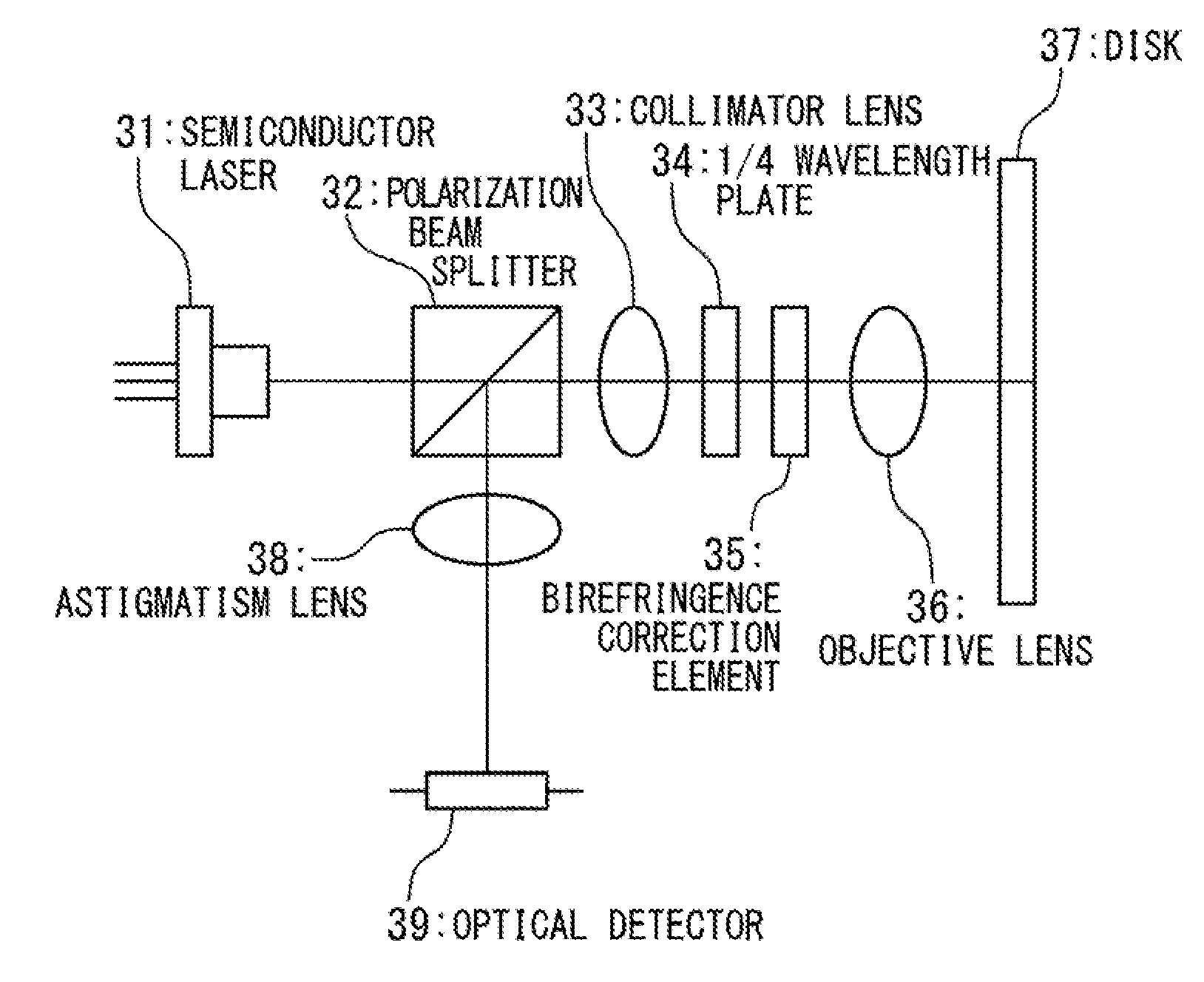
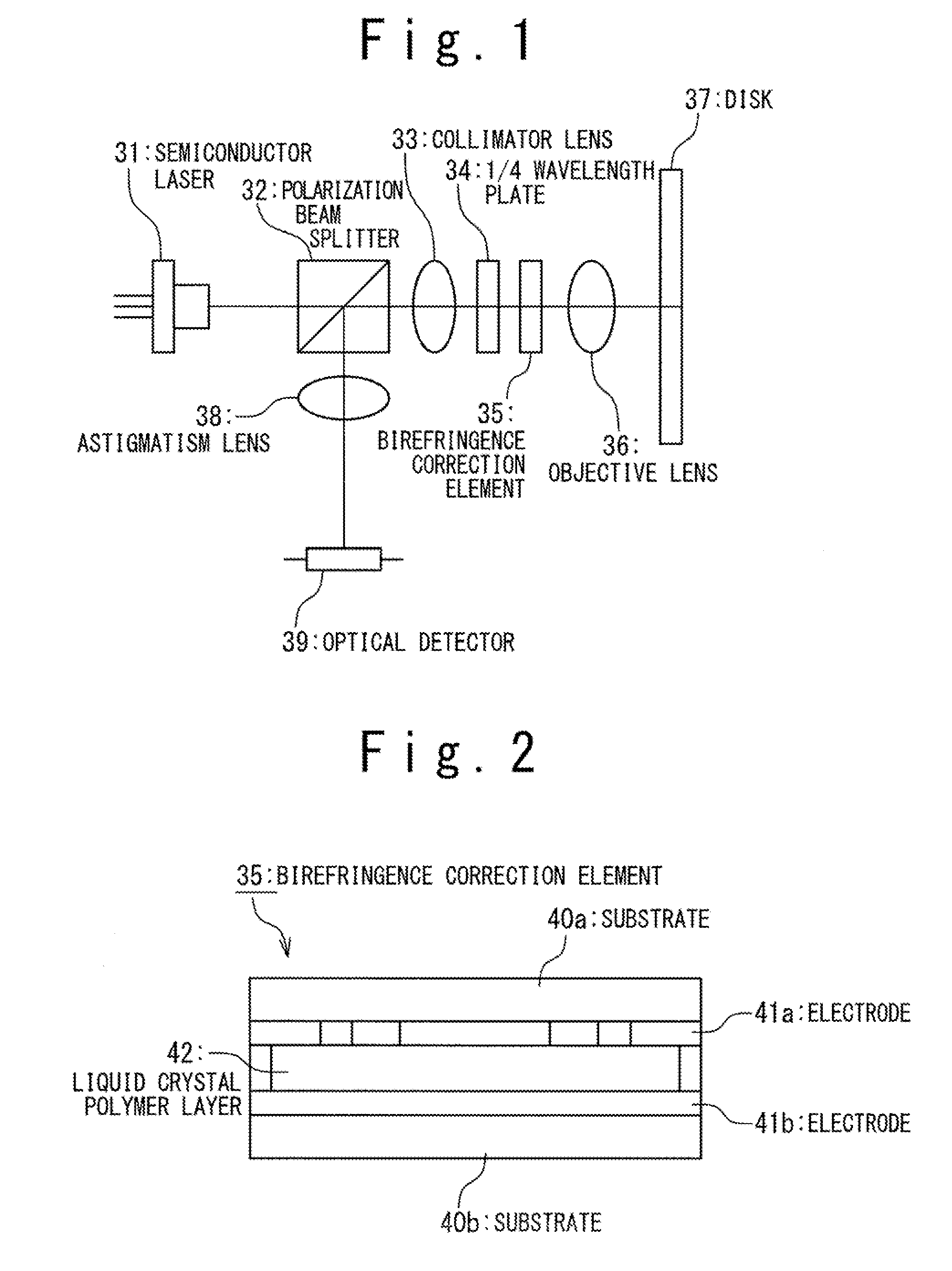
[0049]FIG. 9 shows a configuration of an optical head device according to a first exemplary embodiment of the present invention. The optical head device 61 includes a semiconductor laser 1, a collimator lens 2, a polarization beam splitter 3, a ¼ wavelength plate 4, a birefringence correction element 5a, objective lenses 6a and 6b, a cylindrical lens 8, a convex lens 9, and an optical detector 10.

[0050]Light emitted from the semiconductor laser 1 which serves as a light source is converted from divergent light into parallel light by the collimator lens 2, is incident on the polarization beam splitter 3 as P-polarization and transmits through the splitter at a rate of nearly 100%, is converted from linearly-polarized light into circularly-polarized light by the ¼ wavelength plate 4, transmits through the birefringence correction element 5a which serves as birefringence correction means...


PUM

PropertyMeasurementUnit
thicknessaaaaaaaaaa
thicknessaaaaaaaaaa
thicknessaaaaaaaaaa

Abstract

In front of the objective lens of an optical head deice, a birefringence correction element (5a) having a first birefringence correcting section consisting of a liquid crystal polymer layer (15a) and electrodes (14a, 14b), a second birefringence correcting section consisting of a liquid crystal polymer layer (15b) and electrodes (14c, 14d), and a third birefringence correcting section consisting of a liquid crystal polymer layer (15c) and electrodes (14e, 14f) is provided. The first birefringence correcting section corrects the impact of vertical birefringence of the protective layer in an optical recording medium variable depending on the kind of an optical recording medium, and the second and third birefringence correcting sections correct the impact of the recording medium protective layer in-plane birefringence that varies by the kind of the optical recording medium.

Description

TECHNICAL FIELD[0001]The present invention relates to an optical head device and an optical information recording / reproducing device for carrying out recording and reproducing on plural types of optical recording media each having different optical condition for use or different optical characteristics of the recording mark. The present application claims the benefit of the priority based on Japanese Patent Application No. 2007-85347 and the disclosures of Japanese Patent Application No. 2007-85347 are hereby incorporated by reference into the present application.BACKGROUND ART[0002]As an optical system of an optical head device for carrying out recording and reproducing on an optical recording medium, the optical system called the polarization optical system is generally used. The optical head device includes a light separation part for separating light emitted from a light source from light reflected from an optical recording medium. In the polarization optical system, light incid...

Claims


Application Information

Patent Timeline
Patent Type & Authority Applications(United States)
IPC IPC(8): G02F1/13G11B7/135
CPCG11B2007/0006G11B7/1369
Inventor KATAYAMA, RYUICHI
Owner NEC CORP
Why Eureka
Try Eureka