
Heated hose apparatus and method

Inactive Publication Date: 2008-12-04
TELEFLEX FLUID SYSTEMS INC
View PDF16 Cites 34 Cited by
  • Summary
  • Abstract
  • Description
  • Claims
  • Application Information

AI Technical Summary

Benefits of technology

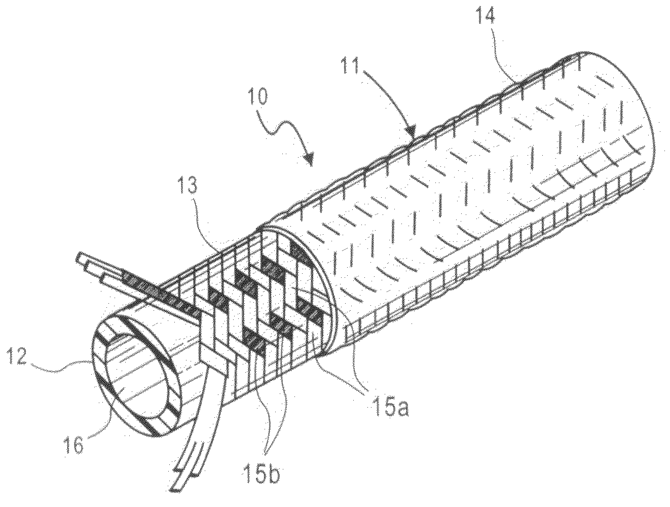
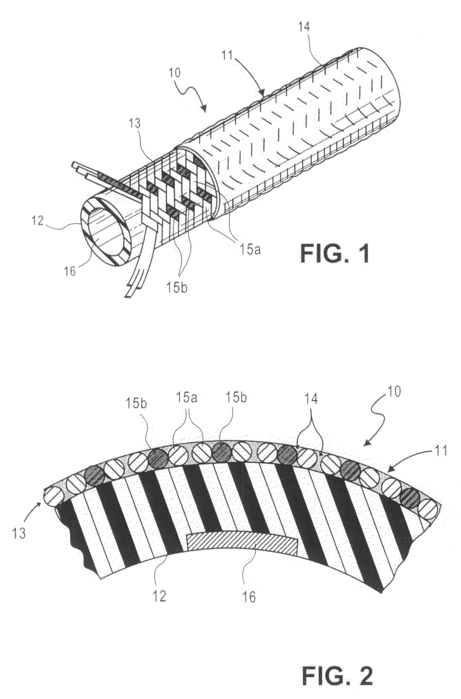
[0009]The foregoing needs are met, to a great extent, by the present invention, wherein in one aspect an integral heated hose apparatus and method is provided that in some embodiments, nonmetallic strengthening material, such as glass fibers may be threaded or braided together with heating wires to form a single unitary layer, which may be attached to the inner liner of the tube. This improved design allows for decreased manufacturing steps, and therefore decreased production costs, for a heated fluid line or the like. The heated hose of the present invention is also less susceptible to wear or breakage in the field. Preferred embodiments of the present hose assembly does not include additional components for attaching the heating wires, such as adhesive tape.

Problems solved by technology

In the fuel-related systems, fluid stream hoses are subject to not only chemical breakdown due to the various fluids that pass through them but are also subject to breakdown from the heat radiating from the engines or exhaust pipes to which the hoses are connected.
However, use of adhesive to attach the wires has drawbacks.
First, the process can be time-consuming and messy.
Second, during operation, the adhesive or adhesive tape can wear and breakdown, especially when the hose is positioned in close proximity to fuel engines, increasing the likelihood of the hose failing to heat the fluid flowing therethrough.
An additional drawback of the currently available heated hose assemblies is that adhesive cannot be used to attach heating wires to an inner liner that is made essentially of fluorocarbon polymers because it will be infeasible to cause the adhesive to stick.
As such, their manufacture is limited to other materials, which typically may not be used to manufacture hoses that may be cut.
Thus, these other materials may only be used to make hoses of specific lengths.
This length-specific construction can be very limiting and increases production costs.
However, in manufacturing these heated hoses, the heating wires and the strengthening layer are typically attached to the hose apparatus requiring separate manufacturing steps.
The additional manufacturing step adds cost to the end product.

Method used


Image

  • Heated hose apparatus and method
  • Heated hose apparatus and method
  • Heated hose apparatus and method

Examples


Embodiment Construction

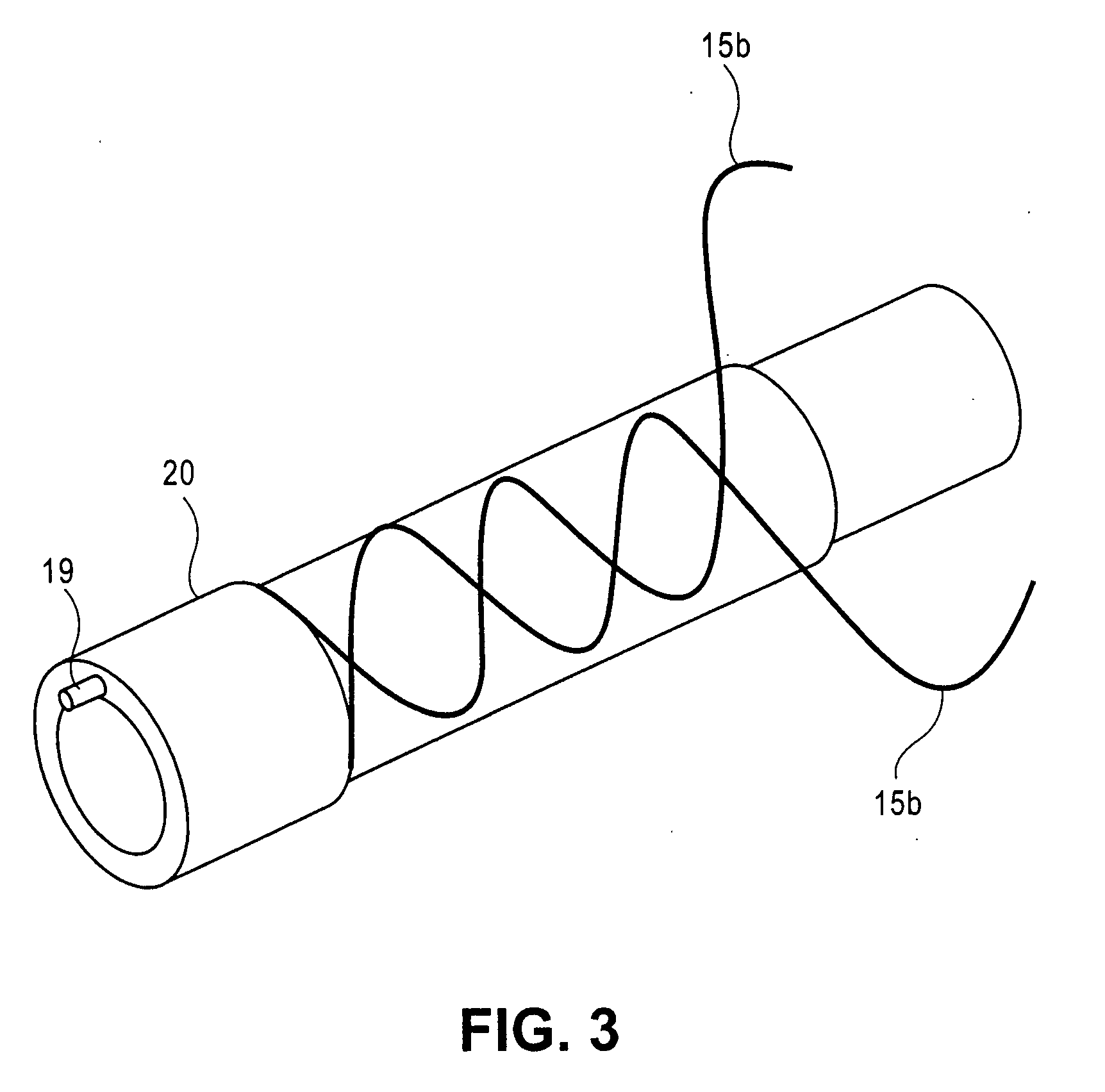
[0020]The invention will now be described with reference to the drawing figures. Example embodiments of the heated hose of the present invention provide heating wires braided or threaded together with a strengthening material around the inner liner. Essentially, rather than attaching wires to a hose, the present invention provides a heating mechanism that is an integral component of the outer layer of the hose. The integration of the glass fibers with the heating wires allows the glass fibers and heating wires to be added in a single manufacturing step to form a lightweight hose assembly adapted for carrying treated exhaust treatment fluid and other fluids that need to be heated. Furthermore, the wire is braided, not wound, which may provide increased hoop strength for high pressure applications.

[0021]The present invention provides an integral heated hose, having a braided layer, which includes heated element wires and glass fibers. The aforementioned braided layer is advantageous b...


PUM


Abstract

A heated hose assembly includes: an extruded inner liner; an intermediate layer comprising strands of a nonmetallic material and at least one heating wire each of the nonmetallic material and heating wire interwoven about the exterior of the extruded inner liner; an outer coating dispersed throughout the strands of the intermediate layer, and; a crimp attachment component for attaching the at least one heating wire to a power source.

Description

FIELD OF THE INVENTION[0001]The present invention relates generally to a heated hose apparatus and method. More particularly, the present invention relates to an apparatus and method for preventing freezing of fluid streams, such as exhaust treatment fluid or the like, by transporting the fluid within a heated hose apparatus.BACKGROUND OF THE INVENTION[0002]Hose assemblies used to carry fluid streams are well known in the art. Preferably, these hoses are strong and resistant to heat and chemical degradation. In the fuel-related systems, fluid stream hoses are subject to not only chemical breakdown due to the various fluids that pass through them but are also subject to breakdown from the heat radiating from the engines or exhaust pipes to which the hoses are connected.[0003]It is known in the art that urea solutions, such as “AdBlue”, may be added as a reactant for reducing the amount of nitrogen oxides (NOx) in combustion exhaust streams, especially diesel fuel exhaust. The urea re...

Claims


Application Information

Patent Timeline
IPC IPC(8): H05B3/58
CPCF01N2610/02F01N2610/10F01N2610/14F16L53/008H05B3/58F16L53/38
Inventor MARTUCCI, NORMAN S.HAHN, RICH
Owner TELEFLEX FLUID SYSTEMS INC
Learn More