Machine retarder

a retarder and machine technology, applied in the direction of fluid couplings, positive displacement liquid engines, couplings, etc., can solve the problems of premature wear of the braking system, increased rotational speed of the power source, and machine may develop significant momentum

Active Publication Date: 2008-12-04
CATERPILLAR INC
View PDF20 Cites 19 Cited by
  • Summary
  • Abstract
  • Description
  • Claims
  • Application Information

AI Technical Summary

Benefits of technology

[0008]In one embodiment, the present disclosure is directed to a system for controllably absorbing energy associated with a machine. The system may include a power source configured to provide power to a hydraulic pump, wherein the hydraulic pump is configured to provide a flow of fluid to a hydraulic dissipation circuit and to one or more implement system hydraulic cylinders, and wherein the hydraulic dissipation circuit is configured to generate a load associated with the hydraulic pump. The system further may include at least one valve configured to provide the flow of fluid to the hydraulic dissipation circuit in response to one or more control signals and a controller configured to receive an input signal from an operator actuated device, and provide the one or more control signals based on the input signal.
[0009]In another embodiment, the present disclosure is directed to a method for controllably absorbing energy associated with a machine. The method may include receiving an input signal indicative of a desired braking force from an operator actuated device, and generating one or more control signals based on the input signal. The method further may include providing the one or more control signals to at least one device configured to modify a flow of fluid in a hydraulic dissipation circuit, wherein the hydraulic dissipation circuit is configured to generate a load associated with the hydraulic pump, and wherein the flow of fluid is generated by a hydraulic pump operatively connected to a power source associated with the machine, and wherein the hydraulic pump is configured to provide the flow of fluid to at least the hydraulic dissipation circuit and to one or more implement system hydraulic cylinders.
[0010]In yet another embodiment, the present disclosure is directed to a machine. The machine may include a frame, a power conversion unit mounted to the frame, a traction device operatively connected to the power conversion unit, and a variable displacement hydraulic pump configured to provide a flow of fluid to a hydraulic dissipation circuit and to one or more implement system hydraulic cylinders, wherein the hydraulic dissipation circuit is configured to generate a load associated with the hydraulic pump. The machine may further include a power source operatively connected to the frame, the traction device, and the variable displacement hydraulic pump, at least one valve configured to provide the flow of fluid to the hydraulic dissipation circuit in response to one or more control signals, and a controller configured to receive an input signal from an operator actuated device, and provide the one or more control signals based on the input signal.

Problems solved by technology

However, once a machine is underway, the machine may develop significant momentum based on the weight and velocity of the machine, among other things (e.g., potential energy associated with elevation of the machine).
When using engine braking, some of the momentum associated with the machine is transferred back into rotational energy and transmitted through driven traction devices, a power conversion unit, and ultimately to the power source resulting in an increase in rotational speed of the power source.
Dependence on mechanical braking can lead to overheating and premature wear on the braking system.
Engine braking may lead to exceeding the rotational speed constraints of the power source (i.e., over-speeding) and therefore, may cause premature wear and / or damage to the power source.
Therefore, in previous systems, limitation of mechanical braking and the over-speeding condition have been accomplished via use of a fluid coupling (i.e., a torque converter) between the power source and the power conversion unit.
This fluid coupling may absorb a portion of the momentum associated with the machine and convert it into fluid heat energy and / or rotational energy, but may be insufficient to fully retard the motion of the machine.
Further recent changes to power conversion units have, in some cases, eliminated the fluid coupling between the power source and the power conversion unit, thus resulting in even greater potential for over-speed of the power source and substantial reliance on mechanical braking systems.
Such reliance may lead to substantial wear and early failure of components associated with the power source and mechanical braking systems.
Such an increase in pressure thereby increases the load on the engine and affects a retarding of the engine.
Although the system of the '386 patent may retard the engine upon an over-speed condition, the '386 patent is limited in that the control occurs only upon an over-speed event, thus leading to greater reliance on mechanical braking systems unless the over-speed condition occurs.
In other words at any time an over-speed condition has been met, the system of the '386 patent causes a retarding of the machine, thereby leading to potential degradation in machine performance when it is desired to increase the engine speed beyond the predetermined value even for short periods of time.

Method used


Image

  • Machine retarder
  • Machine retarder
  • Machine retarder

Examples


Embodiment Construction

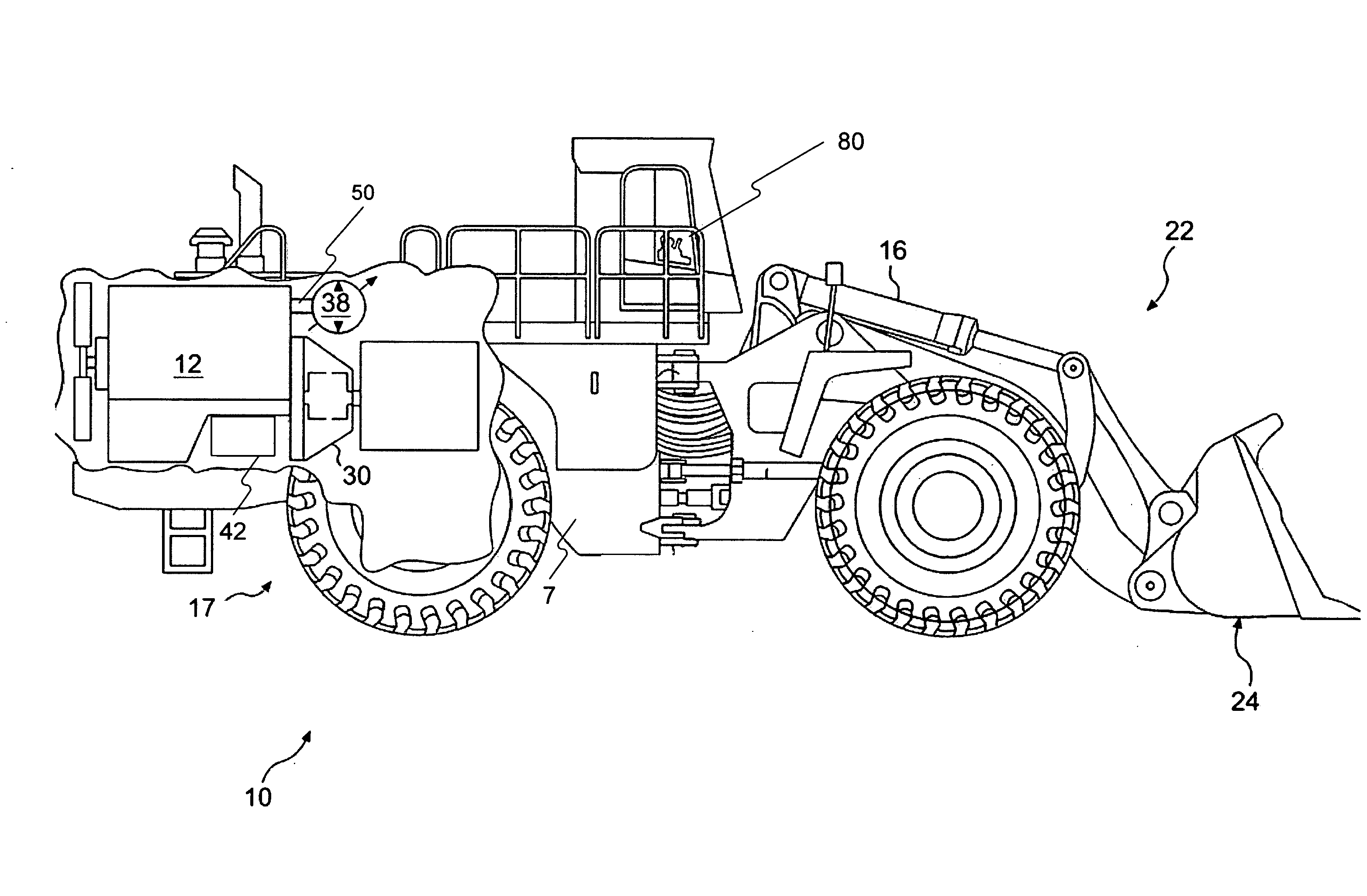
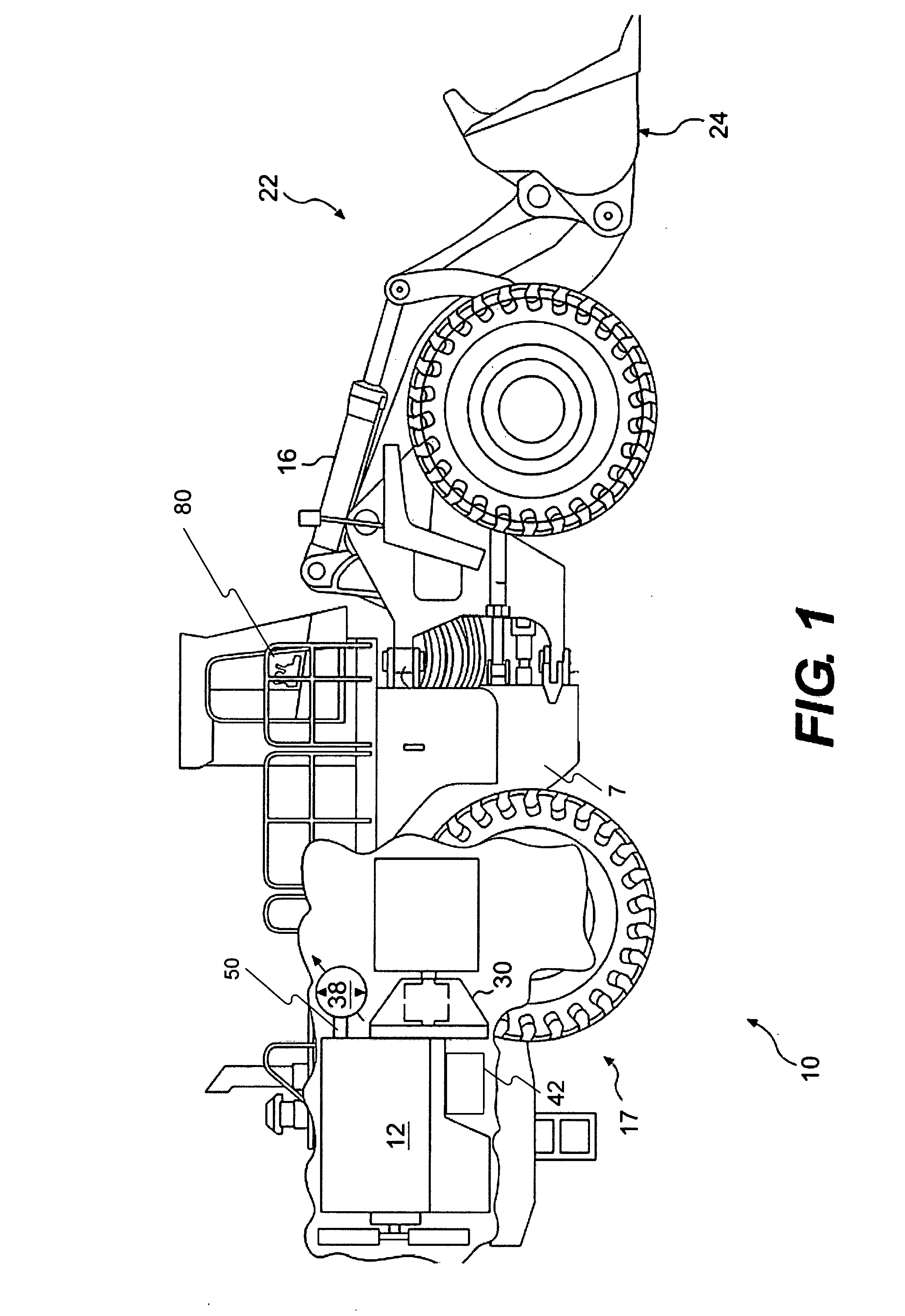
[0014]FIG. 1 illustrates an exemplary embodiment of a machine 10. Machine 10 may be a mobile machine that performs some type of operation associated with an industry such as mining, construction, farming, or any other industry known in the art. For example, machine 10 may be an earth moving machine such as a wheel loader, a dump truck, a backhoe, a motor grader, or any suitable machine. Machine 10 may include a power source 12, a frame 7, an operator interface 80, at least one hydraulic circuit 200 (not shown in FIG. 1) including hydraulic pump 38, and a power conversion unit 30 connected to at least one driven traction device 17. Machine 10 may further include one or more implement systems 22, a cooling package (not shown), and a mechanical braking system (not shown).

[0015]Power source 12 may be an engine such as, for example, a diesel engine, a gasoline engine, a gaseous fuel powered engine such as a natural gas engine, or any other engine apparent to one skilled in the art. Power...


PUM


Abstract

A system is provided for controllably absorbing energy associated with a machine. The system may include a power source configured to provide power to a hydraulic pump, wherein the hydraulic pump is configured to provide a flow of fluid to a hydraulic dissipation circuit and to one or more implement system hydraulic cylinders, and wherein the hydraulic dissipation circuit is configured to generate a load associated with the hydraulic pump. The system may also include at least one valve configured to provide the flow of fluid to the hydraulic dissipation circuit in response to one or more control signals and a controller configured to receive an input signal from an operator actuated device, and generate the one or more control signals based on the input signal.

Description

TECHNICAL FIELD [0001]The present disclosure relates generally to retarding of a machine, and more particularly, to dissipating energy associated with motion of a machine through a hydraulic retarding mechanism.BACKGROUND [0002]Machines such as, for example, dozers, loaders, excavators, motor graders, and other types of heavy machinery utilize power sources to accomplish tasks including motion of the machine and operation of an implement driven by an implement pump. These power sources have limited rotational speed ranges measured in rotations per minute (RPM) and are often linked to one or more power conversion units, which may in turn be operatively connected to one or more driven traction devices with the goal of imparting motion to the machine through use of the rotational energy.[0003]However, once a machine is underway, the machine may develop significant momentum based on the weight and velocity of the machine, among other things (e.g., potential energy associated with elevat...

Claims


Application Information

Patent Timeline
Patent Type & Authority Applications(United States)
IPC IPC(8): F04B49/00F16H61/4157
CPCB60T10/04
Inventor JURICAK, STEVEN J.LAFOREST, BRADLEY J.MILKOWSKI, ARTHURSPIELMAN, MICHAEL A.
Owner CATERPILLAR INC
Why Eureka
Try Eureka