Resurfacing reamer with cutting struts

a technology of resurfacing reamer and cutting strut, which is applied in the field of surgical instruments, can solve the problems of increasing precision and reducing surgical time, and achieve the effects of reducing surgical time, increasing the precision of the result, and reducing cutting torqu

Active Publication Date: 2008-12-04
VIANT AS&O HLDG LLC
View PDF4 Cites 167 Cited by
  • Summary
  • Abstract
  • Description
  • Claims
  • Application Information

AI Technical Summary

Benefits of technology

[0008]An advantage of the invention is a combination handle and inverted (concave-type) reamer system wherein the reamer tool is a single integrated part which requires fewer operative steps to accomplish an analogous result at a work site relative to other reamer systems. This thereby reduces surgical time and increases precision of the result at the work site over other reamer systems. This result is accomplished by a structural design combining different types of cutting teeth that engage the work site at different angles to provide a work result having multiple surfaces cut in distinctly different plains. Additionally, the design of cutting teeth enables a lower cutting torque and allows cutting on multiple surfaces simultaneously.
[0009]Another object of the invention is to provide a guided means of cutting and shaping the bulbous bone of a joint (e.g., a hip joint) to reduce the risk of damaging it in the shaping process. A further object of the invention is to provide a system which enables controlled cutting and reshaping of the bulbous end of a joint bone in preparation for closely receiving a bone joint prosthetic cap.

Problems solved by technology

This thereby reduces surgical time and increases precision of the result at the work site over other reamer systems.

Method used


Image

  • Resurfacing reamer with cutting struts
  • Resurfacing reamer with cutting struts
  • Resurfacing reamer with cutting struts

Examples


Embodiment Construction

[0023]Referring now to the drawings, the details of preferred embodiments of the present invention are graphically and schematically illustrated. Like elements in the drawings are represented by like numbers, and any similar elements are represented by like numbers with a different lower case letter suffix.

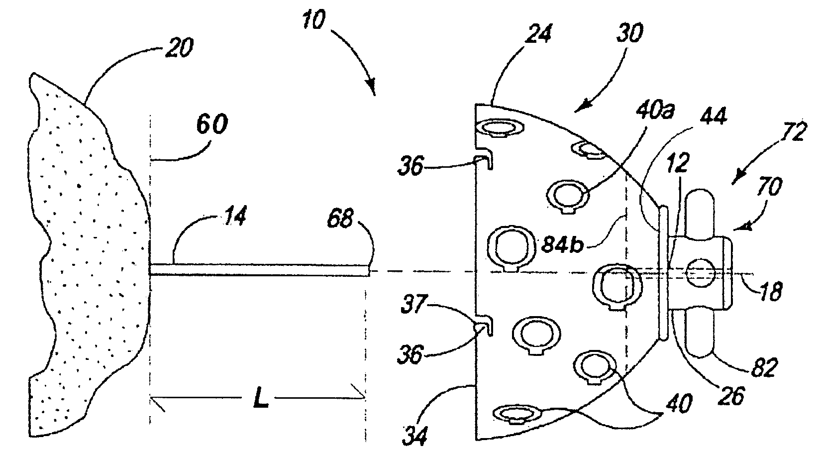
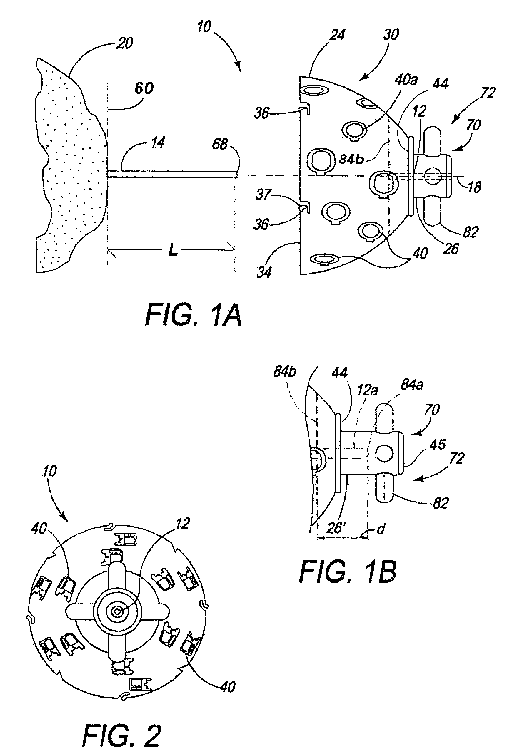
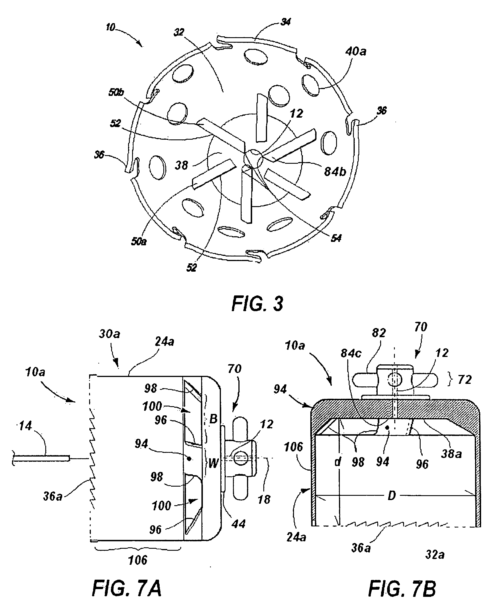
[0024]As shown in FIGS. 1A-1B and FIG. 2, the present reamer 10 has a profile cutting head portion 30 and an axial guide assembly 70 portion. The cutting head includes a profile cutting form 24. “Profile cutting form” as used herein means that this portion of the reamer 10 cuts a profile shape or form 21, 21a (see FIG. 5B) in relief into the bone 20, the relief shape projecting from the bone and having a symmetric profile. The cutting form 24 has a cutting rim 34, inner cutting surface 32 and an apex 38. The apex 38 is opposite the cutting rim 34 and concentric with the rotational axis 18 of the reamer 10. The specific profile shape cut into the bone 20 by the reamer 10 is defined...


PUM


Abstract

Disclosed is a guided orthopedic bone reamer (10a) for cutting a profile relief shape (21a) into a joint bone (20). The reamer (10a) has a cutting head (30a) and an axial guide assembly (70). The cutting head (30a) has a profile cutting form (24a) with a rim (34) and an apex (38a). The apex (38a) connects to the cutting form (24a) by a set of struts (94). An axial guide assembly (70) has one end (44a) fixed to the apex (38a) and at the other end has a bayonet mechanism (76) connectable to a drive handle. Rim cutting teeth (36a) are set into the rim (34) to cut a cylindrical profile (21a), and bevel cutting teeth (96) integral to the struts (94) cut a bevel (25) onto the cylindrical form (21a) cut into the bone (20). A guide pin bore (12a) passes through the apex (38a)and the guide assembly (70) concentric with the axis of rotation (18) to receive a guide pin (14) to guide the reamer (10a) in cutting alignment relative to the joint bone (20) to be cut.

Description

[0001]The present application is a Continuation-in-Part and claims the benefit of prior filed U.S. application Ser. No. 11 / 617,743, filed 29 Dec. 2006, and also claims the benefit of prior filed U.S. Provisional application Ser. No. 60 / 943,849, filed 14 Jun. 2007, which applications are incorporated herein by reference.FIELD OF THE INVENTION[0002]The present invention is in the field of surgical apparatuses used in the treatment of diseases, wounds and other abnormal conditions of the bodies of humans and lower animal (Class 128). Specifically, the present invention relates to orthopedic instrumentation designed for particular use in a surgical procedure on bone structure to correct a deformity, fracture, unwanted or diseased condition Class 606 / subclass 53). More specifically, the present invention relates to a cutting means particularly adapted to assist in the removal of bone tissue (86) on the proximal portion of a femoral head so that a prosthetic member fitted thereto to effec...

Claims


Application Information

Patent Timeline
Patent Type & Authority Applications(United States)
IPC IPC(8): A61B17/00A61F5/00A61B17/58
CPCA61B17/1617A61B17/162A61B17/1637A61B17/1668A61B17/1684A61B17/175A61B2019/304A61B2090/034
Inventor GUELAT, DIDIERLECHOT, ANDRE
Owner VIANT AS&O HLDG LLC
Why Eureka
Try Eureka