Container evacuation system

a container and evacuation system technology, applied in the field of flexible bulk container systems, can solve the problems of increasing likelihood, affecting the complete evacuation of flowable materials, so as to reduce the clogging of the evacuation drain, reduce the viscosity, and improve the recovery rate

Inactive Publication Date: 2008-12-11
PAPER SYST
View PDF8 Cites 18 Cited by
  • Summary
  • Abstract
  • Description
  • Claims
  • Application Information

AI Technical Summary

Benefits of technology

[0013]Advantageously, this invention provides a container evacuation system which provides for higher recovery rate of liquid and semi-liquid products from a container.
[0014]Advantageously, this invention provides a container evacuation system which reduces clogging of an evacuation drain with container material during the evacuation process.
[0015]Advantageously, this invention provides a container evacuation system which allows for the heating of a liquid or semi-liquid product within the container to reduce viscosity and aid in the evacuation process.
[0016]Advantageously, this invention provides a container evacuation system which allows for more positive coupling of an air supply to a container to aid in the evacuation process, and to prevent tearing or ripping of the air supply line from the container.
[0017]In an advantage provided by this invention, a

Problems solved by technology

While such prior art constructions aid in the evacuation of viscous material such as grease and the like, such prior art pockets have certain drawbacks.
One drawback associated with such prior art devices is that the straight weld between the inner pocket and outer pocket positioned below the drain frustrates complete evacuation of the flowable material from the portion of the pocket where the weld meets the edges of the inner pocket and outer pocket.
An additional drawback associated with such prior art devices is that the failure of the system to more completely evacuate the flowa

Method used


Image

  • Container evacuation system
  • Container evacuation system
  • Container evacuation system

Examples


Embodiment Construction

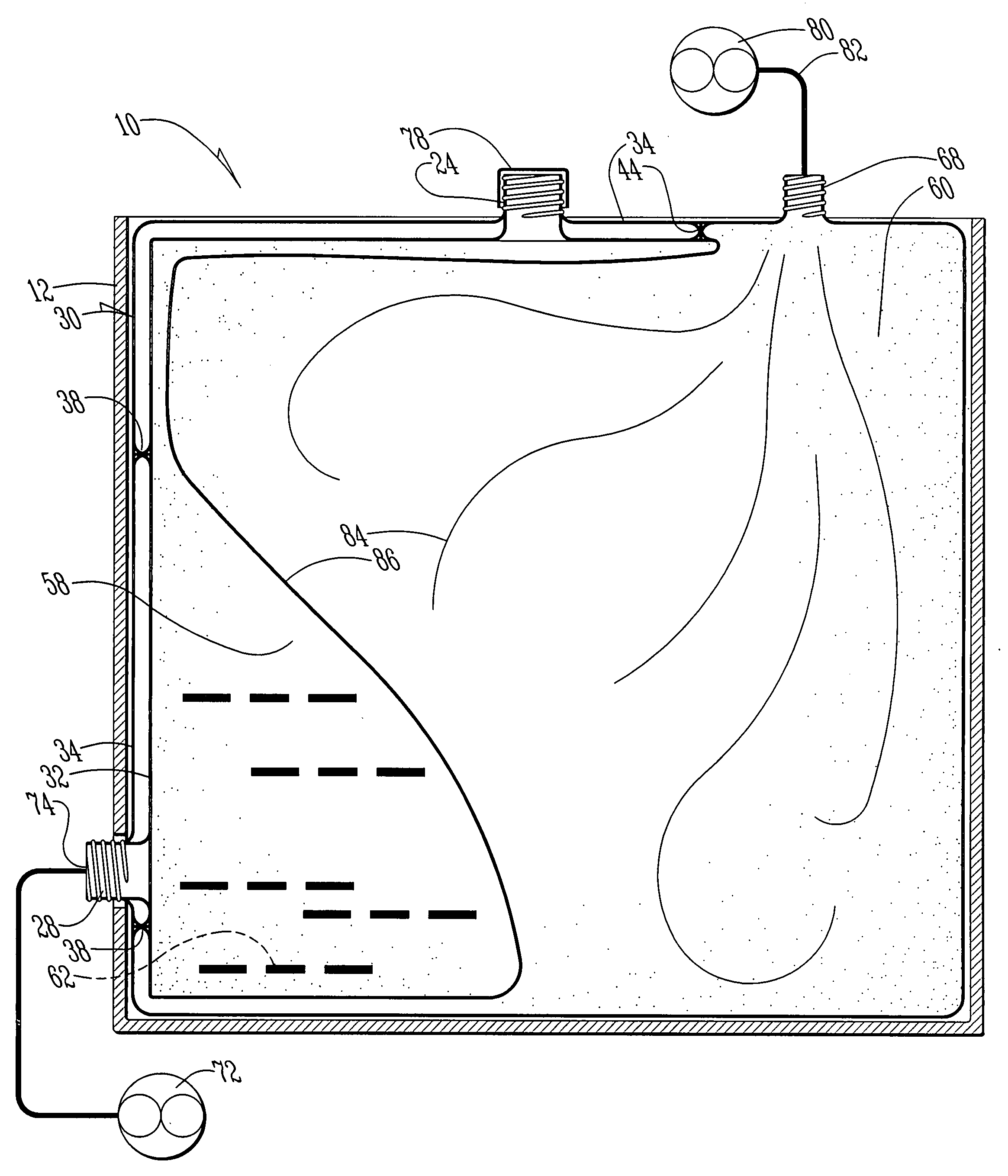
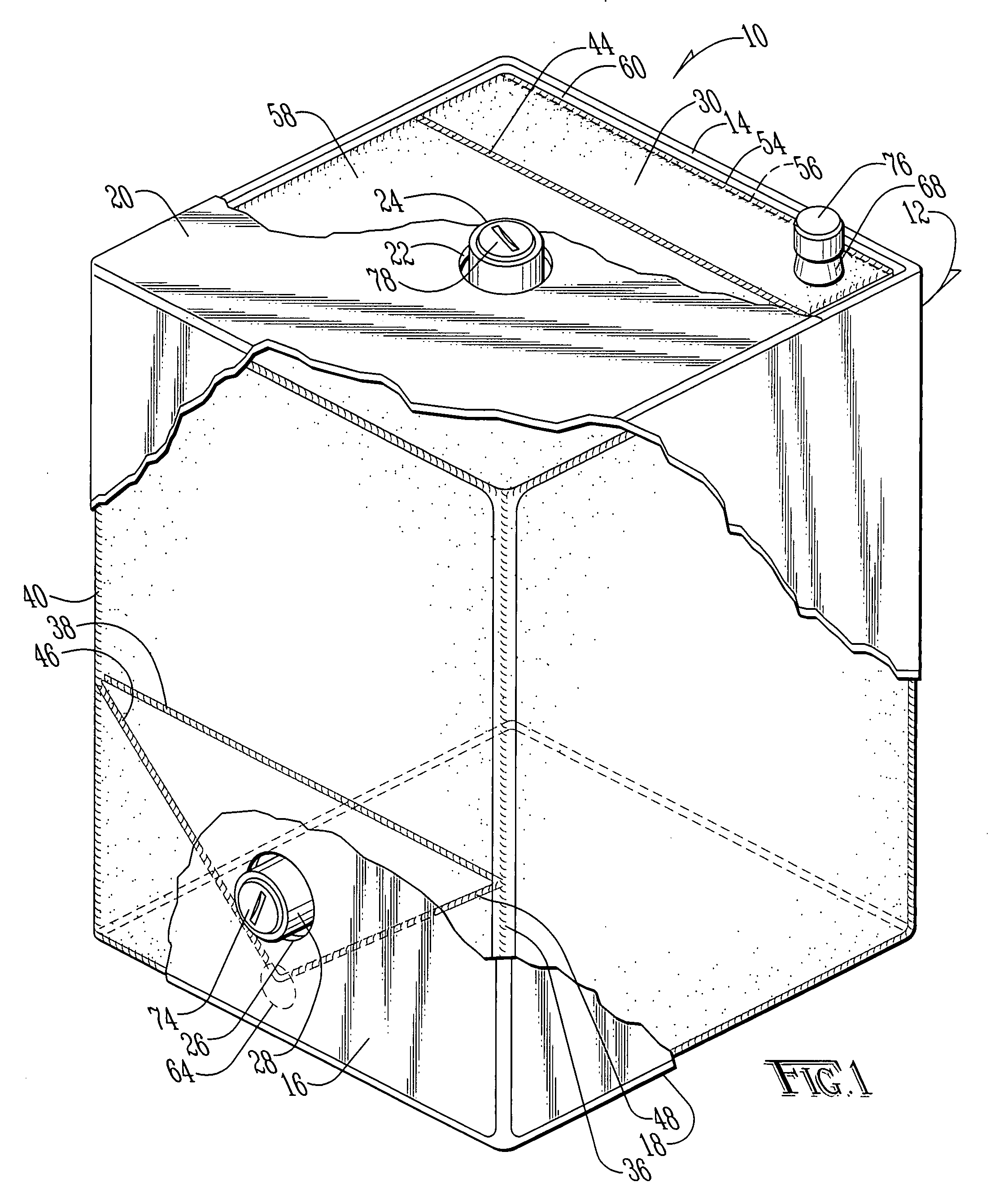
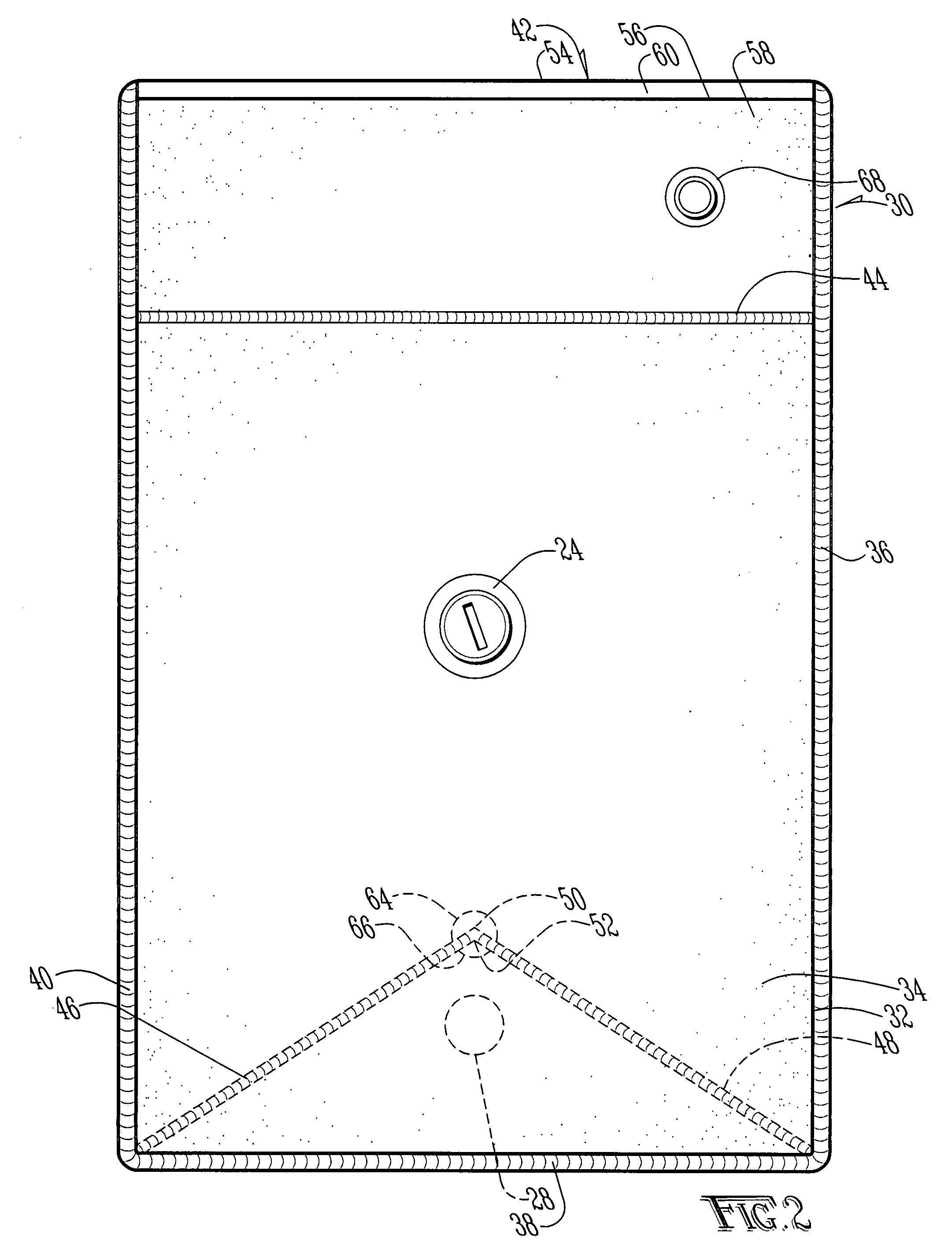
[0025]A container evacuation system according to the present invention is shown generally as (10) in FIG. 1. The system (10) includes a rigid outer container (12) preferably constructed of multiple layers of corrugated cardboard (14). In the preferred embodiment the rigid container (12) is of a generally rectangular box construction. However, the rigid container (12) may be constructed of any suitable material, including, but not limited to, metal, fabric or other textile, and may be utilized in any desired configuration, such as octagonal, cylindrical, or any other desired configuration. In the preferred embodiment, the rigid container (12) may be of any desired volume but, in the preferred embodiment, is preferably between 0.5 and 10.0 cubic meters, and most preferably between 1.0 and 2.0 cubic meters.

[0026]The rigid outer container (12) is provided with a sidewall (16) coupled to a bottom (18) and a top (20). If desired, the top (20) may be removable and provided with a cutout (2...


PUM


Abstract

A container evacuation system is provided for viscous flowable materials such as grease, paste or flowable powders. The container system includes a lightweight, rigid exterior, such as a cardboard container. Provided within the container is a flexible containment system constructed of polyethylene sheets or the like. The flexible containment system is provided with a plurality of weldments to create at least two pockets, wherein one pocket contains the flowable material and a second pocket is available to be filled with air, to allow air provided to the second pocket to force the flowable material from the first pocket out through a drain. The system includes a weldment which curves around at least a portion of the drain to crease a funnel which focuses flowable material toward the drain, while reducing the likelihood of a portion of the flexible containment system from obstructing the movement of flowable material out of the first pocket through the drain.

Description

BACKGROUND OF THE INVENTION [0001]1. Field of the Invention[0002]The present invention relates to bulk containers for flowable materials and, more specifically, to a flexible bulk container system which allows for the more complete evacuation of a viscous material from a container.[0003]2. Description of the Prior Art[0004]It is known in the art when moving viscous material, such as grease and the like, to utilize a container having a rigid exterior frame and a flexible interior pocket. Typically the interior pocket contains a top mounted inlet and a side mounted drain. The pocket is filled from the top inlet, which is capped for transportation and storage. When it is desired to evacuate the container, the drain is opened and the material is allowed to flow out of the container through the drain.[0005]When dealing with viscous materials such as grease, especially when the grease is cooled and thereby less flowable, it is desirable to provide a mechanism for forcing the grease from t...

Claims


Application Information

Patent Timeline
IPC IPC(8): B65D35/28B65D35/56B67D5/42B67D7/60
CPCB65D77/06B67D7/0244B67D7/0255B67D7/3254B67D2001/0828B67D1/0462
Inventor STUART, KEVIN R.
Owner PAPER SYST
Why Eureka
Try Eureka