Mold apparatus for forming polymer and method

a technology of molding apparatus and polymer, which is applied in the direction of manufacturing tools, induction current sources, electric/magnetic/electromagnetic heating, etc., can solve the problems of affecting the surface appearance and cycle time, overheating during processing, and adhesion of parts to the mold cavity, etc., to achieve excellent surface finish, reduce energy consumption, and heat quickly

Active Publication Date: 2008-12-11
SHPP GLOBAL TECH BV
View PDF97 Cites 39 Cited by
  • Summary
  • Abstract
  • Description
  • Claims
  • Application Information

AI Technical Summary

Benefits of technology

[0007]The present invention relates to a mold apparatus and method for forming polymer via induction heating. In one embodiment of the present invention, a mold apparatus for forming polymer includes a mold having a top mold portion and a top mold surface, and a bottom mold portion and a bottom mold surface opposing the top mold surface. The bottom mold portion includes an induction heating unit that is at least partially embedded therein. The top mold surface is a magnetic material which is heated by the induction heating unit located in the bottom mold portion and which causes the polymer to be heated rapidly. The mold apparatus is constructed and arranged to dissipate greater than about 50% of the induction heat energy in the top mold portion. When the top and bottom mold portions are placed together under pressure, the polymer part is formed or molded according to the geometry or configuration of the top and bottom mold surfaces. The close proximity of the induction heating unit to the top mold surface allows for rapid heating and utilizes less energy.
[0008]The induction heating unit of the mold apparatus can includes one or more coils. The at least one coil can generate heat in a single phase, or in alternative embodiments, can generate heat in multi-phases. The coil design, whether single phase or multi-phase, provides for uniform heat distribution along the top mold surface and results in the production of polymer parts having excellent surface finish.
[0009]A method for forming polymer in accordance with the present invention includes placing or injecting the polymer between the top mold surface and the bottom mold surface and heating the top mold surface via an induction heating unit. The top mold surface is heated to a predetermined temperature, for example the heat deflection temperature or the melt temperature of the polymer. Upon reaching the predetermined temperature, the method further includes cooling the polymer in preparation for ejection of the polymer part from the mold. The top and bottom mold surfaces can be further cooled by passing a liquid cooling medium through at least one of the top and bottom and mold portions of the mold. When the top mold surface is cooled to a predetermined ejection temperature, the mold is opened and the formed polymer part is ejected. In another example embodiment, the method further includes passing a gas medium, for example air, through the top and bottom mold portions to purge the liquid cooling medium from the mold during or after ejection of the polymer part. Purging the cooling medium with gas allows the mold to be heated faster during and / or after ejection in preparation for the next polymer part to be formed, thereby reducing cycle time.

Problems solved by technology

Heating and cooling the mold lengthens the cycle time.
When higher power densities are applied in response, then larger thermal gradients, which create hot and cold spots on the mold surface negatively, impact the surface appearance and cycle time.
A problem with the use of magnetic reinforcements is cost, overheating during processing and adhesion of the parts to the mold cavity.
A problem, however, is that this method can be energy-intensive and it can be difficult to control thermal gradients resulting in “hot spots” along the mold surfaces.
A problem is the rate of cooling, as it is very difficult to retract the coil before the mold surface cools below the targeted processing temperature.
Current methods of processing polymers, for example, hand lay-up, vacuum bagging, autoclaving, etc., using reinforced and unreinforced polymers, result in cycle times which are prohibitive and are not being used in higher part volume applications.
Additionally, current methods typically use low-pressure processes which often result in surface finishes which are often inconsistent and require significant rework to make a usable part.
As a result, current methods do not lend themselves to a high-volume production environment.

Method used


Image

  • Mold apparatus for forming polymer and method
  • Mold apparatus for forming polymer and method
  • Mold apparatus for forming polymer and method

Examples


Embodiment Construction

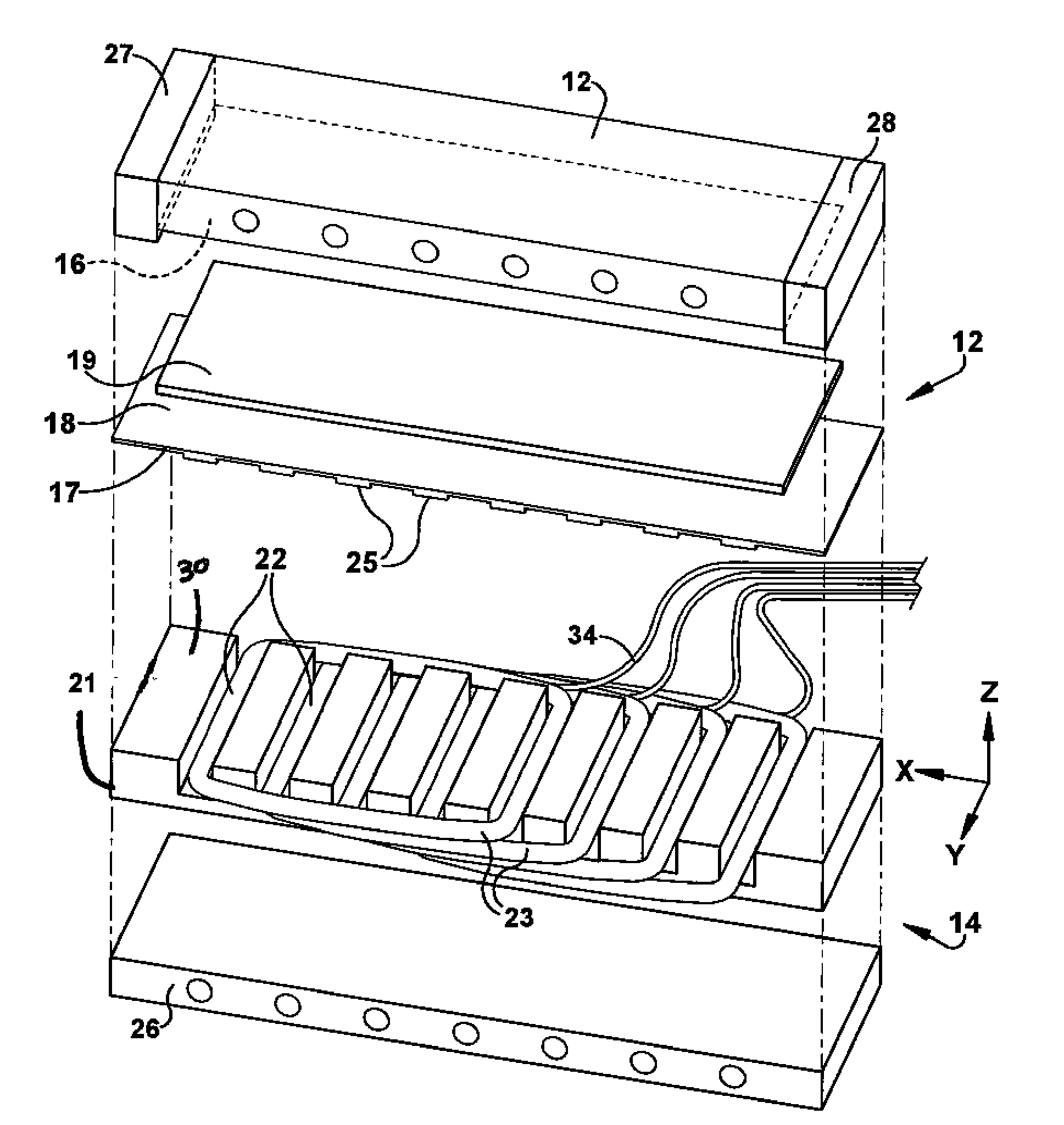
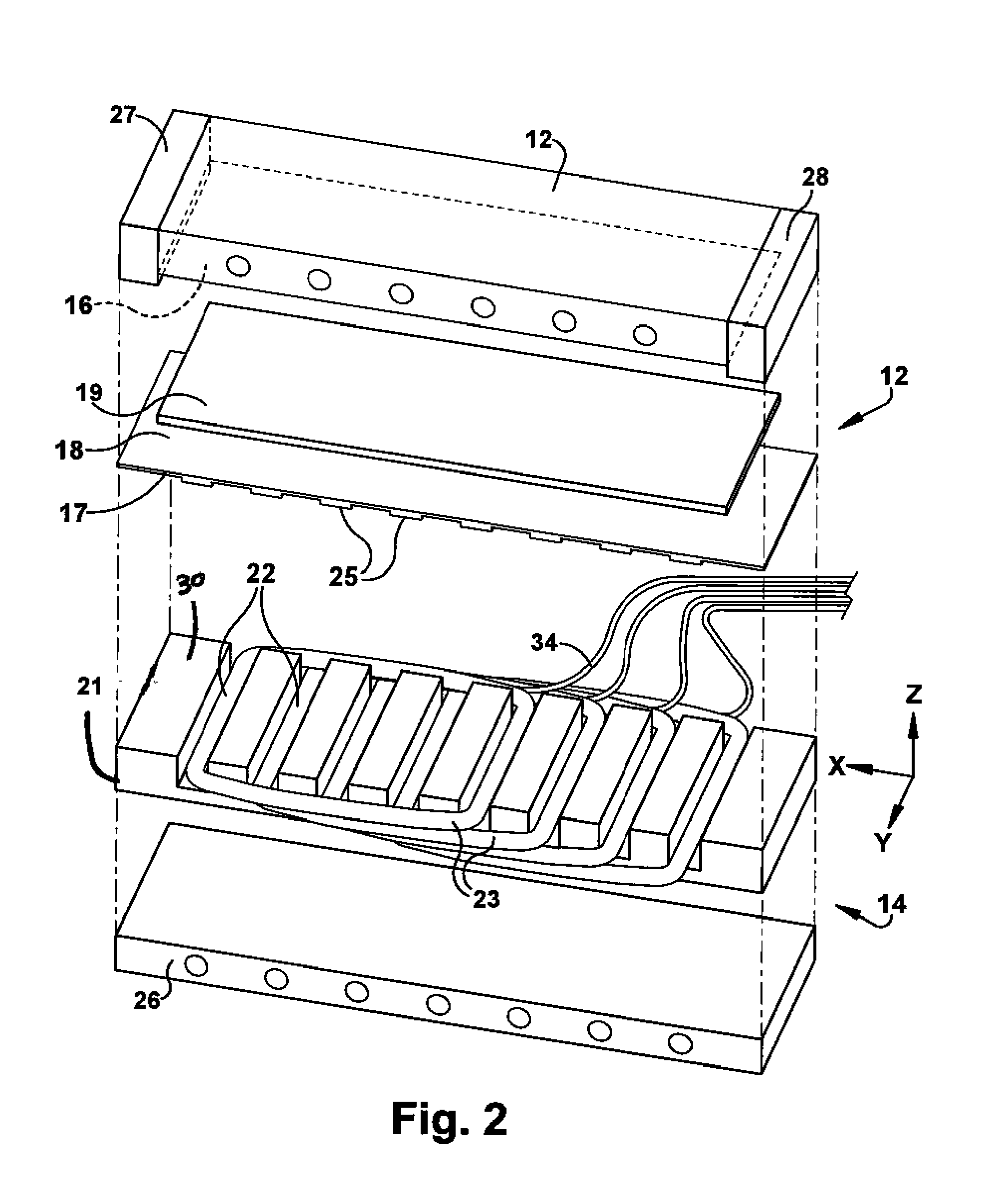
[0019]The present invention provides for a mold apparatus for forming a polymer part via induction heating. Polymer disposed within a mold is formed by inductively heating the mold and the polymer formed by the mold. In one embodiment, one half of the mold which contacts a surface of the polymer includes an induction heating unit which heats the second half of the mold which also contacts another surface of the polymer. The mold apparatus for forming polymer can be used for several types of thermoforming and molding methods. For example, thermoforming methods include vacuum forming, plug assist thermoforming, pressure forming, match metal forming, etc. In addition, the mold apparatus 10 can be used for several types of molding, such as injection molding, compression molding, and plastic stamping.

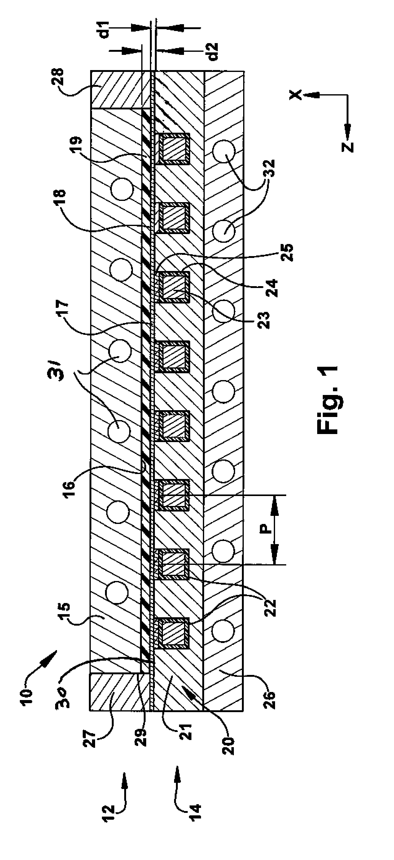
[0020]FIG. 1 is a cross-sectional illustration of a mold apparatus 10 for heating a polymer. The polymer may be an unfilled, neat resin or it may contain reinforcement fibers and / or mineral ...


PUM

PropertyMeasurementUnit
saturation flux densityaaaaaaaaaa
distanceaaaaaaaaaa
distanceaaaaaaaaaa

Abstract

Various mold apparatuses and methods for forming a polymer with induction heat energy are provided. In one embodiment of the present invention, a mold apparatus for forming polymer includes a mold having a top mold portion and a top mold surface that is magnetic. The bottom mold portion of the mold includes an induction heating unit that is at least partially embedded in the bottom mold portion that provides induction heat energy to the mold. The mold apparatus is constructed and arranged to dissipate greater than about 50% of the induction heat energy in the top mold portion. The induction heating unit of the bottom portion of the mold provides rapid heating the top mold surface to provide high surface quality polymer parts a shorter molding cycle time while utilizing less energy.

Description

CROSS REFERENCE TO RELATED APPLICATIONS[0001]This application claims priority to U.S. Provisional Application No. 60 / 942,800, filed Jun. 8, 2007, which is hereby incorporated by reference in its entirety.FIELD OF THE INVENTION[0002]The present invention relates to a mold apparatus for forming polymer into polymer parts and the method of forming polymer parts. More specifically, the present invention relates to a mold apparatus having induction heating capability for forming polymer and a method of forming the polymer by induction heating of the polymer.BACKGROUND OF THE INVENTION[0003]Conventional techniques molding or forming polymer to produce a desired part involve mold temperatures consistently at or below the ejection temperature of the polymer. It has become increasingly desirable to cycle the mold to a higher temperature to improve physical properties or cosmetics for the desired part. This is done by conducting heat to the outer surfaces of the mold by an internal / external s...

Claims


Application Information

Patent Timeline
Patent Type & Authority Applications(United States)
IPC IPC(8): B29C35/12
CPCB29C33/06B29C2035/0816B29C35/0805B29C35/08H05B6/02
Inventor ANBARASU, RAMASAMYDIAS, ASHWITPRAKASH, OMSOWLE, DANIEL
Owner SHPP GLOBAL TECH BV
Why Eureka
Try Eureka