System and Method of the Optical Delay Line

a technology of optical delay line and optical delay line, which is applied in the field of optical delay line system and method, can solve the problems of difficult fabrication, complicated operation, and high cost of traditional optical delay line system, and achieve the effect of avoiding intensity loss and simple fabrication

Inactive Publication Date: 2008-12-11
CHUNG YUAN CHRISTIAN UNIVERSITY
View PDF8 Cites 4 Cited by
  • Summary
  • Abstract
  • Description
  • Claims
  • Application Information

AI Technical Summary

Benefits of technology

[0007]This invention provides a system and a method of the optical delay line, wherein the system of the optical delay line has many advantages as compact, simple fabrication, and avoiding the intensity loss during the above-mentioned scanning. The system comprises a source and an array of mirrors, wherein the array of mirrors comprises a first reflective mirror, a second reflective mirror, a third reflective mirror, and a fourth reflective mirror. Beams from the source could be delayed because the beams are multi-reflected by the reflective mirrors.

Problems solved by technology

However, the traditional system of the optical delay line is always expensive, difficult to fabricate, complicated to operate, and hard to maintain.
However, most of the configurations are difficult to construct or variational intensity loss exists during the scanning because of the walk-off of different wavelength components and different tilted angle of the scanner.

Method used


Image

  • System and Method of the Optical Delay Line
  • System and Method of the Optical Delay Line
  • System and Method of the Optical Delay Line

Examples


Embodiment Construction

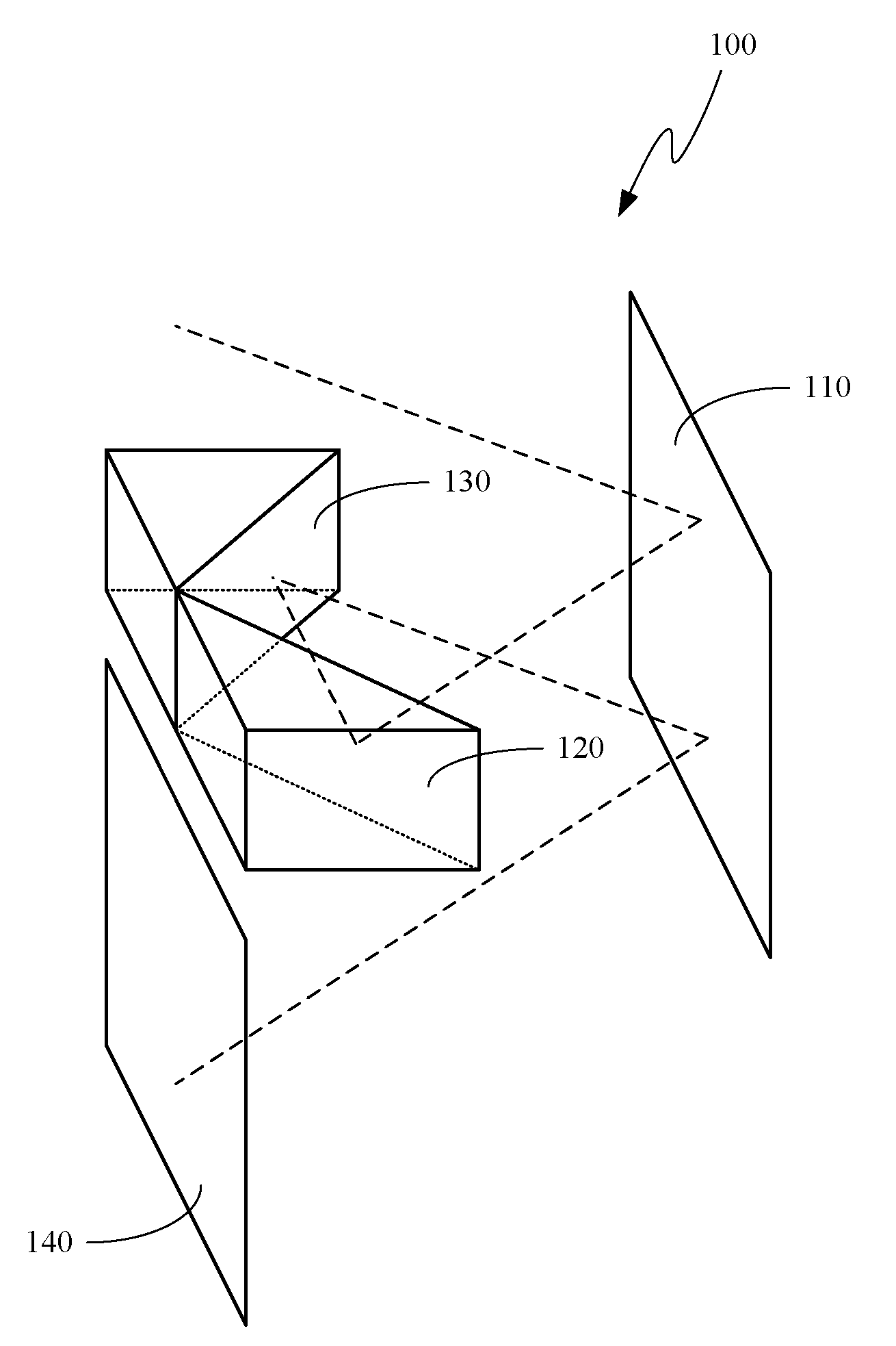
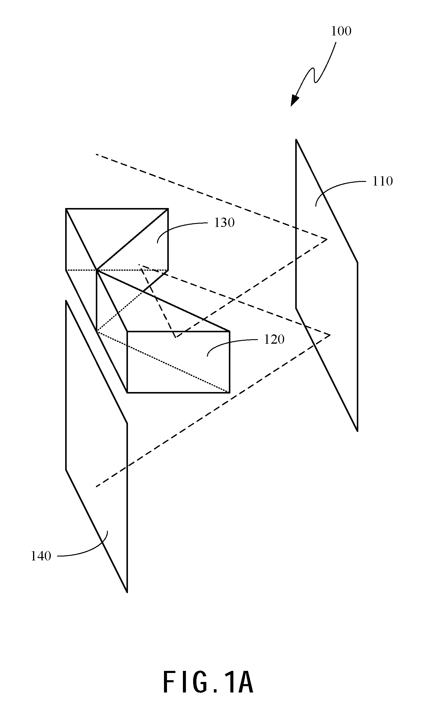
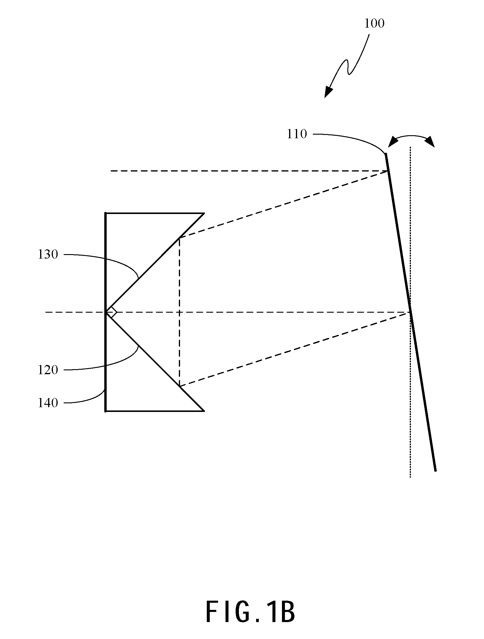
[0014]The present disclosure can be described by the embodiments given below. It is understood, however, that the embodiments below are not necessarily limitations to the present disclosure, but are used to a typical implementation of the invention.

[0015]Having summarized various aspects of the present invention, reference will now be made in detail to the description of the invention as illustrated in the drawings. While the invention will be described in connection with these drawings, there is no intent to limit it to the embodiment or embodiments disclosed therein. On the contrary the intent is to cover all alternatives, modifications and equivalents included within the spirit and scope of the invention as defined by the appended claims.

[0016]It is noted that the drawings presents herein have been provided to illustrate certain features and aspects of embodiments of the invention. It will be appreciated from the description provided herein that a variety of alternative embodimen...


PUM


Abstract

This invention provides a system and a method of the optical delay line, wherein the system comprises a source and an array of mirrors, wherein the array of mirrors comprises a first reflective mirror, a second reflective mirror, a third reflective mirror, and a fourth reflective mirror. Beams from the source could be delayed because the beams are multi-reflected by the reflective mirrors.

Description

BACKGROUND OF THE INVENTION[0001]1. Field of the Invention[0002]The present invention generally relates to system and method of the optical line, and more particularly to system and method of the optical delay line.[0003]2. Description of the Prior Art[0004]It is very important to delay optical line in many fields of optics, such as microscopy, adaptive optics, crystal optics, holography, optical pattern recognition, photometry, radiometry, thin film optics, physiological optics and so on. However, the traditional system of the optical delay line is always expensive, difficult to fabricate, complicated to operate, and hard to maintain. Hence, we urgently need a new system without the above-mentioned defects for applications of sciences.[0005]Beside, one of the most interested aspects in the development of optical delay line technology is to construct a stable and easy fabricated optical delay line that can perform real-time imaging for clinical applications. There are many methods t...

Claims


Application Information

Patent Timeline
Patent Type & Authority Applications(United States)
IPC IPC(8): G02B26/08G02B5/08
CPCG02B17/004G02B17/0856G02B26/06Y10S359/90
Inventor HSU, I-JENKAO, CHIA-YUNLAI, CHENG-CHUNGCHANG, CHAO-MINGHOU, TI-KUANG
Owner CHUNG YUAN CHRISTIAN UNIVERSITY
Why Eureka
Try Eureka