Frequency division communication system

a communication system and frequency division technology, applied in the field of frequency division communication system, can solve the problem of more complex configurations for both the receiver and the transmitter

Inactive Publication Date: 2008-12-11
FUJITSU LTD
View PDF13 Cites 20 Cited by
  • Summary
  • Abstract
  • Description
  • Claims
  • Application Information

AI Technical Summary

Benefits of technology

[0010]Hence an object of this invention is to provide an orthogonal frequency division communication system which, while maintaining adva

Problems solved by technology

This results in more complex configurations

Method used


Image

  • Frequency division communication system
  • Frequency division communication system
  • Frequency division communication system

Examples


Embodiment Construction

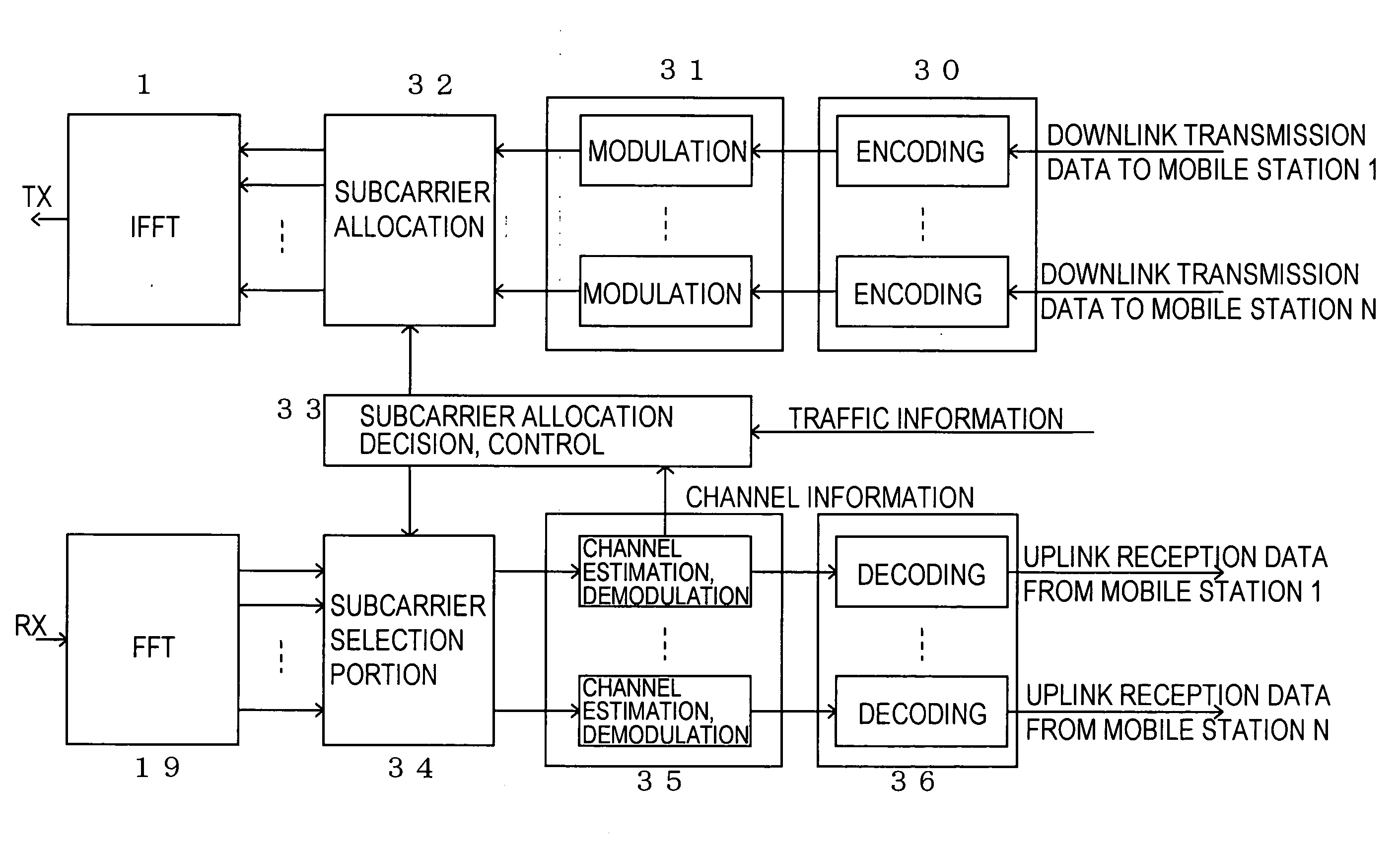
[0037]Below, embodiments of the invention are explained referring to the drawings. The embodiments explained below are intended to facilitate understanding of the invention, and the technical scope of the invention is not limited to these embodiments.

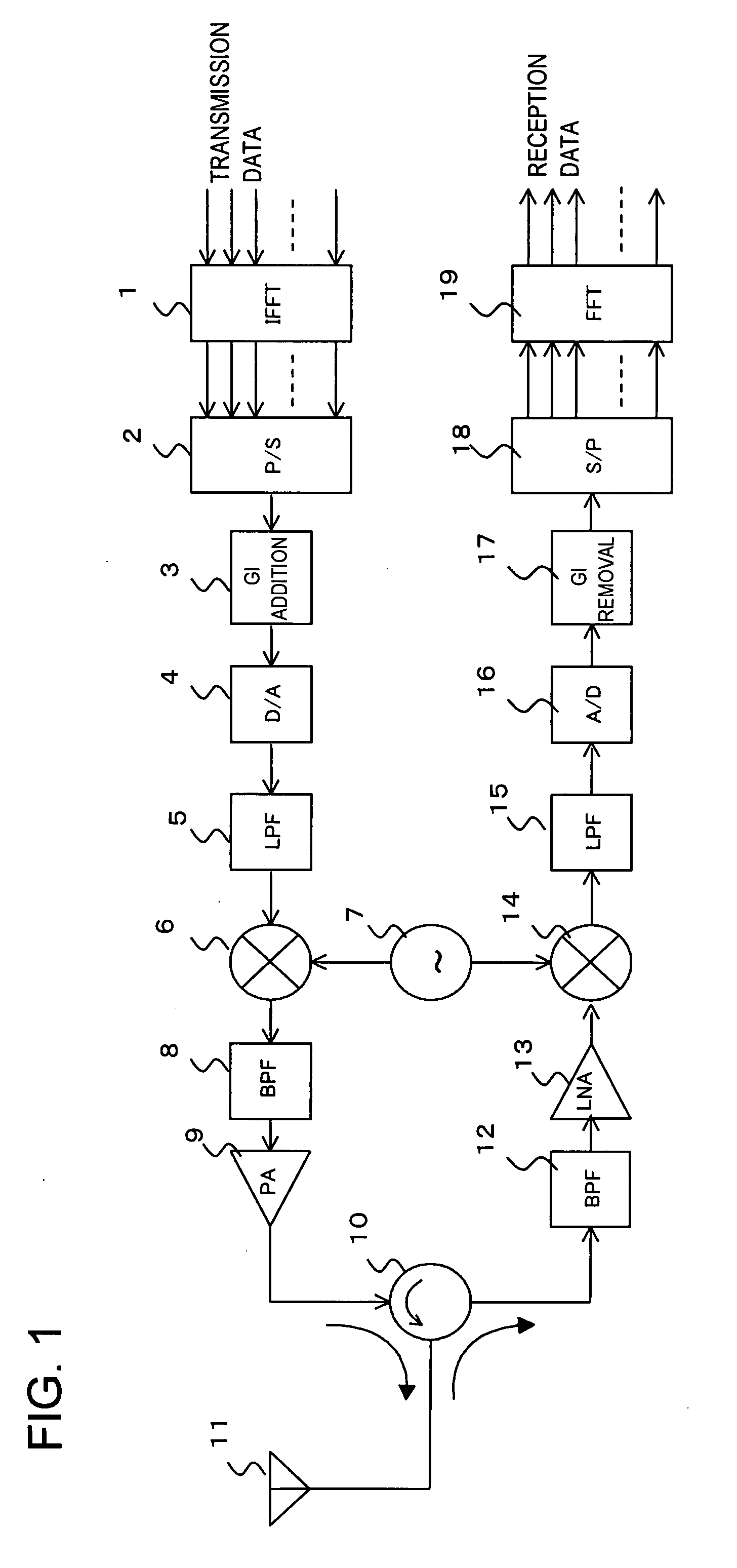
[0038]FIG. 1 explains in summary a general Orthogonal Frequency Division Multiplex (OFDM) method transceiver to which the invention is applied.

[0039]In FIG. 1, transmission data input to the transmitter side is allocated, by bit, to a plurality of subcarriers. Then, the IFFT converter 1 performs an Inverse Fast Fourier Transform (IFFT) to convert signals to the time domain.

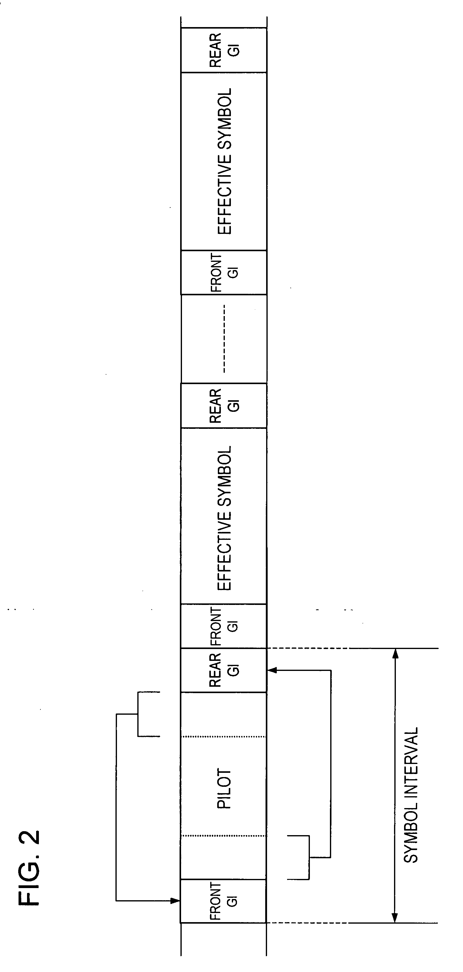
[0040]Signals converted into the time domain are converted into serial signals by the P / S converter 2, and then the guard interval (GI) insertion circuit 3 inserts guard intervals (GIs) at each symbol.

[0041]Here, as indicated in the frame structure ofFIG. 2, guard intervals (GIs) have a front guard interval (GI) which is the portion for a prescribed period copied to t...


PUM


Abstract

An orthogonal frequency division communication system which enables flexible modification of the ratio of allocation between uplink and downlink transmissions, while maintaining advantages similar to those of TDD (Time Division Duplex) systems, has a base station and a plurality of mobile stations connected by uplinks and downlinks, and a plurality of mutually orthogonal frequencies are allocated, on the frequency axis and on the time axis, to the uplinks and downlinks and to the plurality of mobile stations.

Description

CROSS-REFERENCE TO RELATED APPLICATIONS[0001]This application is a continuation of international application PCT / JP2005 / 000399, filed on Jan. 14, 2005.TECHNICAL FIELD[0002]This invention relates to a frequency division communication system for multiplexing uplink and downlink transmission using a plurality of frequencies. In particular, this invention relates to an Orthogonal Frequency Division Multiplexing (OFDM) method in which the relation of frequencies is orthogonal so as to enable effective utilization of the frequencies used.BACKGROUND ART[0003]In the past, communication systems performing radio frequency multiplexing of uplink and downlink transmissions have adopted the Frequency Division Duplex (FDD) method or the Time Division Duplex (TDD) method.[0004]Further, in third-generation mobile telephone systems, TDD methods adopted in TDS (Time Division Synchronous)-CDMA (Code Division Multiple Access) and other systems have enabled effective use, compared with FDD methods used ...

Claims


Application Information

Patent Timeline
IPC IPC(8): H04Q7/00H04B1/707H04B7/26H04J3/00H04J11/00H04W72/04H04W88/02
CPCH04L5/0007H04L5/0023H04L5/0046H04L5/0048H04L5/006H04L5/143
Inventor KIMURA, DAIDATEKI, TAKASHISAWAMOTO, TOSHIROMINOWA, MORIHIKO
Owner FUJITSU LTD
Why Eureka
Try Eureka