Optical communication system using wdma and CDMA

Inactive Publication Date: 2008-12-11
HITACHI LTD
View PDF2 Cites 72 Cited by
  • Summary
  • Abstract
  • Description
  • Claims
  • Application Information

AI Technical Summary

Benefits of technology

[0027]According to the invention, with the combined use of optical CDMA and the principles of WDMA, it is possible to avoid the interference between light waves (influence of beat noise) which is an obstacle to the pra

Problems solved by technology

In optical CDMA, when a plurality of communication devices transmit CDMA signals with carrier waves (laser beams) of a same wavelength on a same optical fiber, mutual interference occurs between transmission signals.
If two optical transmission signals in completely opposite phase exist on an optical fiber, the optical signals are canceled out by mutual interference, so that signal strength on the

Method used


Image

  • Optical communication system using wdma and CDMA
  • Optical communication system using wdma and CDMA
  • Optical communication system using wdma and CDMA

Examples


Embodiment Construction

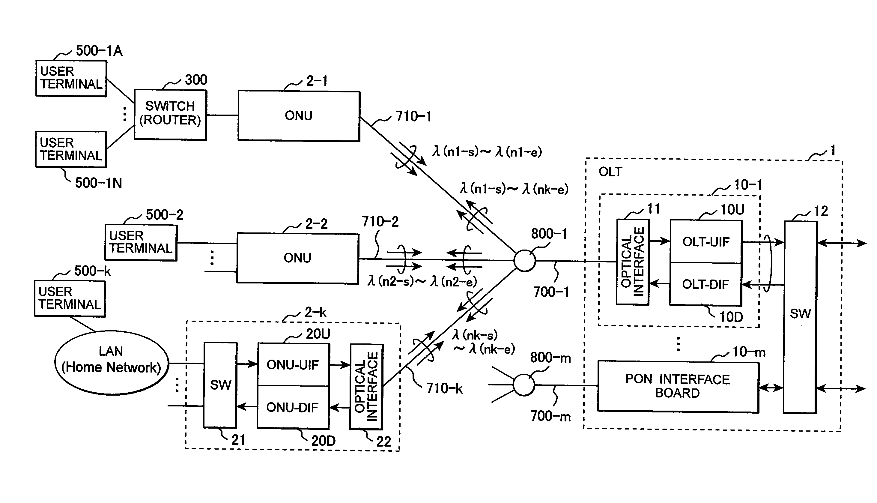
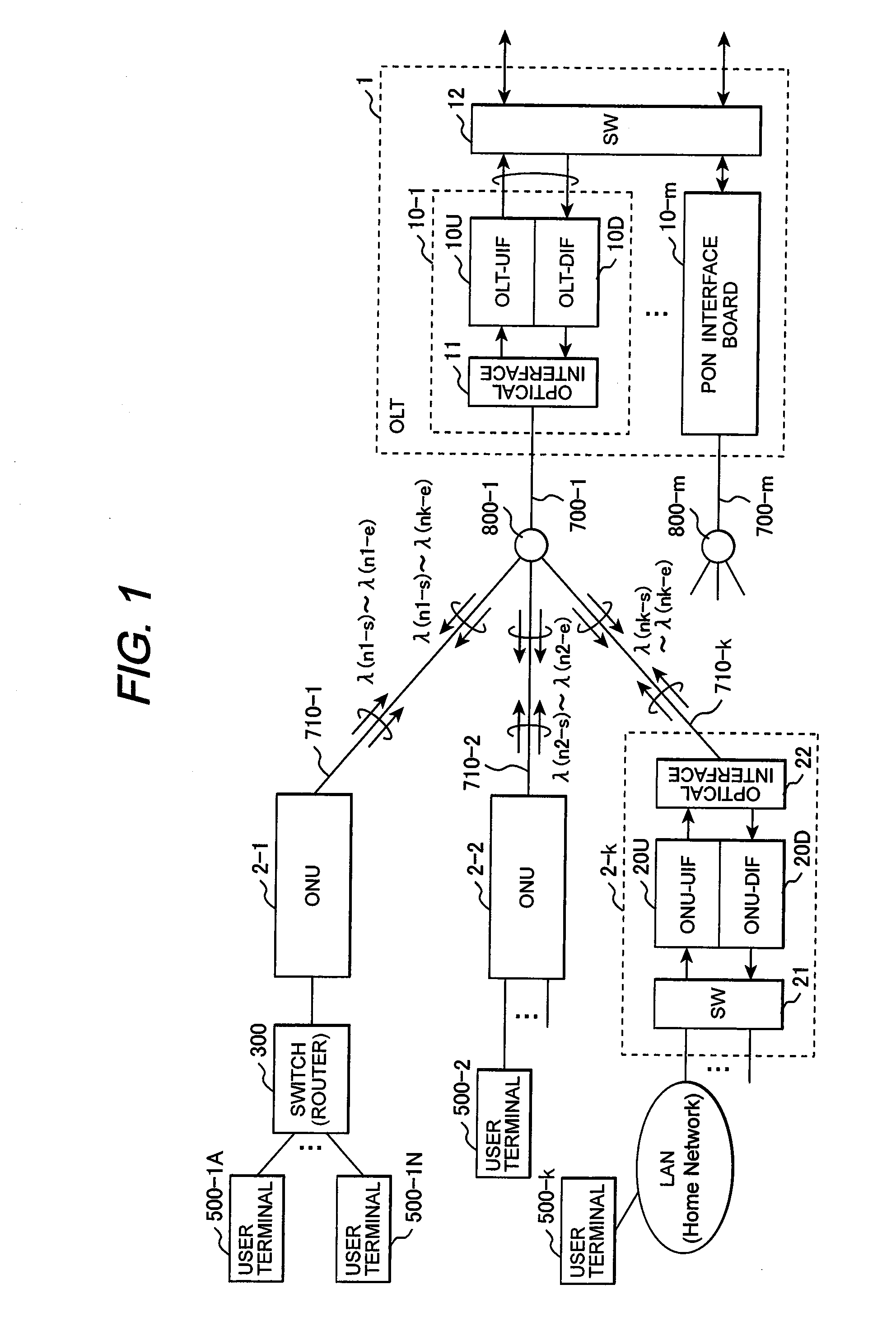
[0046]FIG. 1 shows the configuration of a PON system to which optical CDMA according to the present invention is applied and carrier wavelengths (carrier frequencies) in an optical fiber section.

[0047]The PON system is comprised of an office side line terminal apparatus OLT (Optical Line Terminal) 1 and a plurality of subscriber connection apparatuses ONU (Optical Network Unit) 2 (2-1 to 2-k) connected to the OLT 1 via an optical fiber network. The optical fiber network is composed of trunk optical fibers 700 (700-1 to 700-m) connected to the OLT 1 and a plurality of branch optical fibers 710 (710-1 to 710-k) connected to a trunk optical fiber 700 through an optical splitter (optical coupler) 800 (800-1 to 800-m). Each ONU 2 is connected to one of the branch optical fibers 710, and a plurality of ONUs share the trunk optical fiber 700 to communicate with the OLT 1.

[0048]One or a plurality of user terminals 500 are connected to each ONU 2. User terminals 500 are connected to the ONU ...


PUM


Abstract

In a PON system, an OLT periodically transmits a channel resource information block specifying a carrier wavelength and a spreading code on a first downstream channel to which a spread-spectrum spreader having a first spreading code is applied; one of ONUs receives the channel resource information block with a spread-spectrum despreader having the first spreading code and transmits a connection request to the OLT, using the carrier wavelength and the spreading code specified by the channel resource information block; the OLT having received the connection request transmits a new channel resource information block specifying a carrier wavelength and a spreading code to be used on an upstream data channel to the requester ONU through the first channel; and the requester ONU transmits data, using the carrier wavelength and the spreading code specified by the new channel resource information block.

Description

CLAIM OF PRIORITY[0001]The present application claims priority from Japanese application Ser. No. 2007-151846, filed on Jun. 7, 2007, the content of which is hereby incorporated by reference into this application.BACKGROUND OF THE INVENTION[0002](1) Field of the Invention[0003]The present invention relates to an optical communication system, and more particularly, to an optical communication system using wavelength division multiple access (WDMA) and code division multiple access (CDMA) in an optical fiber section.[0004](2) Description of the Related Art[0005]Services on a communication network have become increasingly diversified, and new services taking advantage of the network have been expanding. A representative example thereof is the integration of broadcasting and communication services such as so-called triple-play service for integrating broadcasting, internet and telephone (audio communication) services. This is a representative application of existing information services...

Claims


Application Information

Patent Timeline
IPC IPC(8): H04J13/02H04B1/707H04B1/7073H04B10/27H04J14/00H04J14/02H04J14/04H04J14/06
CPCH04B1/707H04B2201/70715H04J14/005H04J14/0226H04J14/0282H04Q11/0067H04Q2011/0064H04Q2011/0086H04J14/0246H04J14/0247H04J14/025H04J14/0252H04J14/0257H04J14/0258H04J14/0267H04J14/0269
Inventor MIZUTANI, MASAHIKOSUGAWARA, TOSHIKIKAZAWA, TOHRUASHI, YOSHIHIRO
Owner HITACHI LTD
Why Eureka
Try Eureka