[0015]The invention provides a transmission belt that has increased
power transmission efficiency and sufficient durability, using elements that are easily formed by an ordinary press operation.
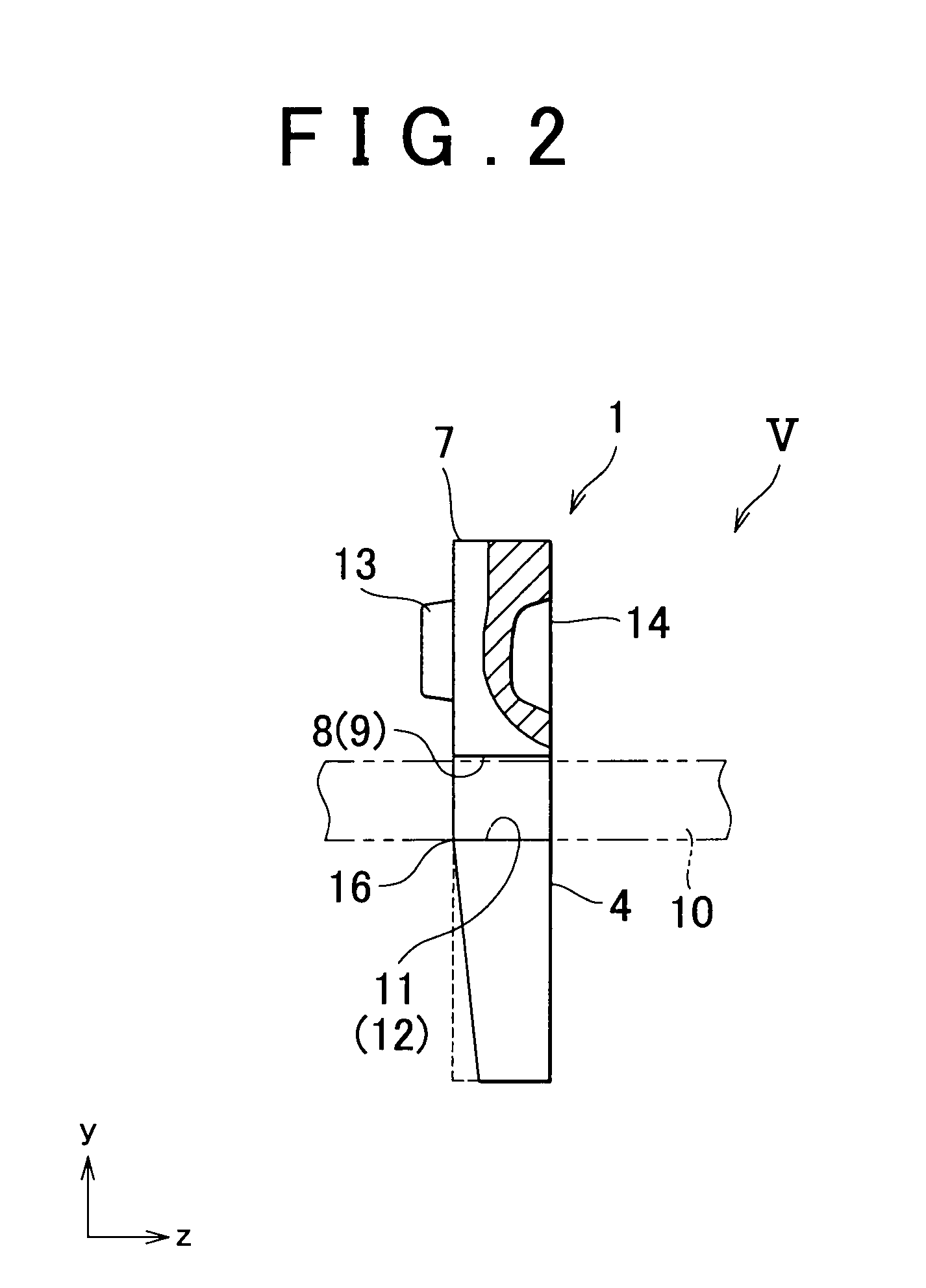
[0019]According to the above-described aspect, the rocking edge is formed on the side surface on which the burr is formed when the element (the first element, the second element) is formed by a press operation such as a
punching operation, that is, the side surface on which the shear droop is not formed when the press operation is performed, and therefore, a sharp edge can be formed. Accordingly, the sharp rocking edge is formed in the element, without being affected by the shear droop that is formed when the press operation is formed. Therefore, it is possible to form the surface that contacts the inner
peripheral surface of the ring, for example, when the elements are wound on the ring, and the rocking edge at the substantially same position in the height direction of the element. This reduces a
relative slip between the inner
peripheral surface of the ring and the element. Thus, it is possible to reduce frictional loss due to the
relative slip, thereby increasing the transmission efficiency of the transmission belt.
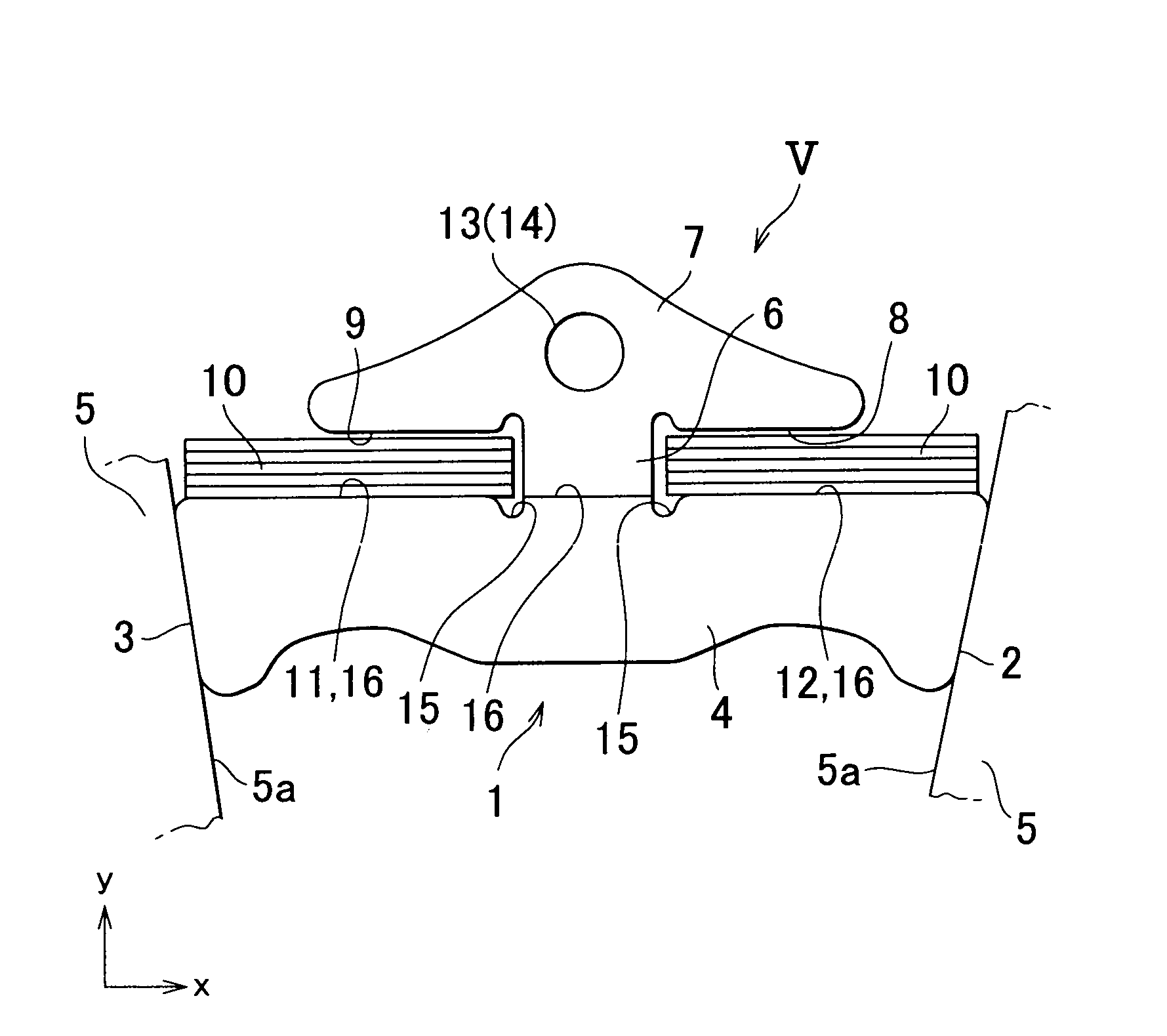
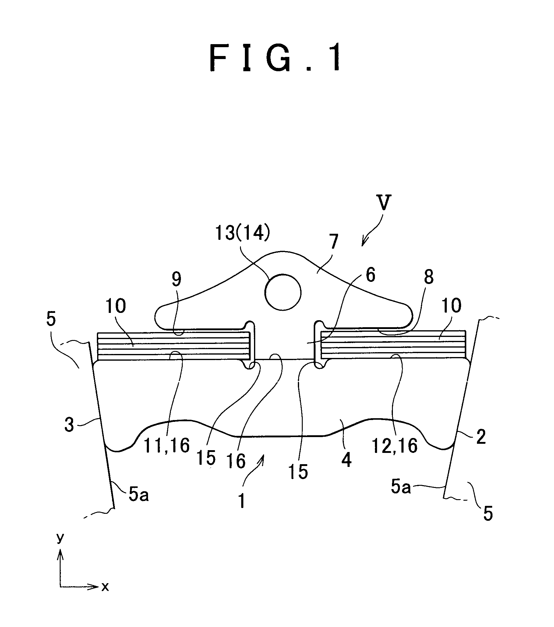
[0020]Also, because the sharp rocking edge is formed in the element without being affected by the shear droop that is formed when the press operation is performed as described above, there is no variation in the plate thickness or level in a portion in which the rocking edge is formed. The transmission belt is formed by the two types of the elements that face in the directions opposite to each other in a direction in which the elements are arranged. That is, the transmission belt is formed by the two types of the elements, that is, the first element and the second element. In the first element, the sharp rocking edge is formed on a front surface that faces forward in a direction in which the transmission belt rotates when the transmission belt is wound on the pulleys to transmit power between the pulleys. In the second element, the sharp rocking edge is formed on a rear surface that faces rearward in the direction in which the transmission belt rotates. Therefore, by arranging the first element and the second element in a manner such that the front surface of the first element faces the rear surface of the second element, it is possible to make the first element and the second element contact each other at the sharp rocking edges. As a result, if a force in a tangential direction is transmitted to each of the end surfaces of the element, and a
bending moment in a front-back direction is applied to the element when torque is transmitted by the transmission belt, the
bending moment is not extremely large, and
stress concentration does not occur, because the elements adjacent to each other contact each other at the rocking edges that extend in the entire width of the element, and there is no variation in the plate thickness or level in the portion in which the rocking edge is formed. This ensures sufficient durability of the element, that is, sufficient durability of the transmission belt.
[0021]Also, the
saddle surface that contacts the inner
peripheral surface of the ring when the ring is wound in the element, and the rocking edge are formed at the same or the substantially same position in the height direction of the element. In this case, a
radius of the transmission belt wound on the
pulley, that is, a distance from a center of the pulley on which the transmission belt is wound to the inner peripheral surface of the ring is substantially equal to a distance from the center of the pulley to the rocking edge. This reduces a difference between a frictional force between the element and the ring, and a frictional force between the element and the pulley. As a result, it is possible to reduce a relative slip between the inner peripheral surface of the ring and the element, which occurs due to the difference in the frictional force. Accordingly, it is possible to reduce frictional loss due to the relative slip, thereby increasing the transmission efficiency of the transmission belt.
[0022]When the first elements and the second elements are alternately arranged, the front surface of the first element faces the rear surface of the second element. In other words, the rear surface of the first element faces the front surface of the second element. That is, the first elements and the second elements are alternately arranged in the following manner. The first element and the second element, which are adjacent to each other, contact each other at the sharp rocking edges. Also, the first element and the second element, which are adjacent to each other, contact each other at the entire side surfaces that are uniformly flat, and that are opposite to the side surfaces on which the rocking edges are formed. Therefore, for example, if a force in a tangential direction is transmitted to each of the end surfaces of the element from the pulley, and a
bending moment in a front-back direction is applied to the element when torque is transmitted by the transmission belt, the bending moment is not extremely large, and
stress concentration does not occur, because the elements adjacent to each other contact each other at the rocking edges that extend in the entire width of the element, and there is no variation in the plate thickness or level in the portion in which the rocking edge is formed. This ensures sufficient durability of the element, that is, sufficient durability of the transmission belt.
