Method and apparatus for magnetic induction therapy

a magnetic induction therapy and energy-emitting technology, applied in the field of energy-emitting apparatus and methods, can solve the problems of nearly 30% or 4 million individuals being reportedly unsatisfied with their current therapy, each of these treatments exhibits severe limitations, and the economic cost of oab and ui is estimated to be in excess of $12 billion

Inactive Publication Date: 2008-12-11
EMKINETICS
View PDF102 Cites 256 Cited by
  • Summary
  • Abstract
  • Description
  • Claims
  • Application Information

AI Technical Summary

Benefits of technology

[0029]It is an object of the present invention to provide apparatus and methods for magnetic induction therapy, i...

Problems solved by technology

The economic cost of OAB and UI is estimated to be in excess of $12 billion a year in the United States alone.
Of those 13.6 million Americans seeking medical treatment, nearly 30% or 4 million individuals are reportedly unsatisfied with their current therapy.
Known treatments for OAB and UI include exercise and behavioral modifications, pharmacological therapies, surgical intervention and neuromodulation, but each of these treatments exhibits severe limitations.
While this type of treatment may be a viable option for a small group of highly dedicated individuals, its daily impact on a person's life makes it unattractive for most patients.
Unfortunately, patients often suffer from side effects related to their drug therapies.
Such side effects are sometimes serious and are particularly pronounced in elderly patient populations that tend to use a plurality of medications.
In addition, approximately 30% of all patients subjected to pharmacological therapies appear to be dissatisfied with the efficacy of their prescribed treatments.
Surgical intervention is extremely invasive and often results in a long-term requirement for catheterization that may become permanent in some instances.
The negative impact of these procedures on the patient's quality of life and their high expense make surgical intervention a recommended option only when all other treatment options have been exhausted.
The authors used a large magnetic field produced by a single coil to ensure that the nerve was fired and the resulting nerve conduction was frequently painful or intolerable.
In addition, coil alignment was problematic because an internally implanted coil was utilized, which had to be aligned with the fully external magnetic field to stimulate the nerve.
Due to the difficulty in positioning the device, the practical application of this therapy does not permit home healthcare usag...

Method used


Image

  • Method and apparatus for magnetic induction therapy
  • Method and apparatus for magnetic induction therapy
  • Method and apparatus for magnetic induction therapy

Examples


first embodiment

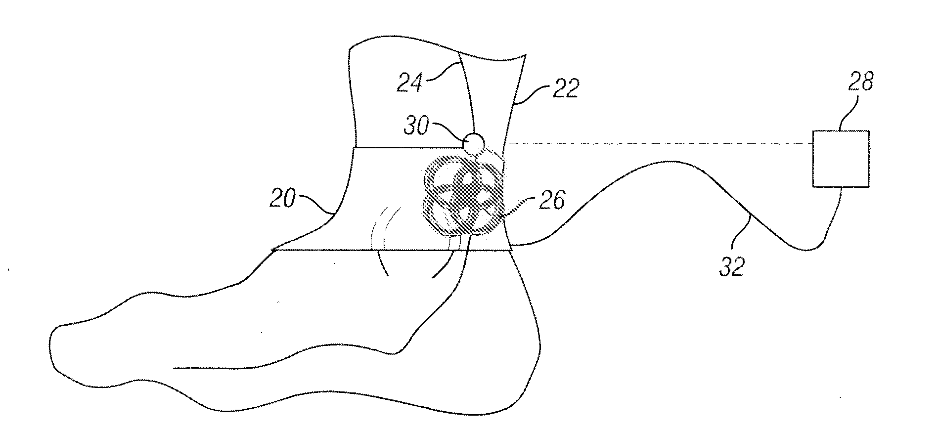
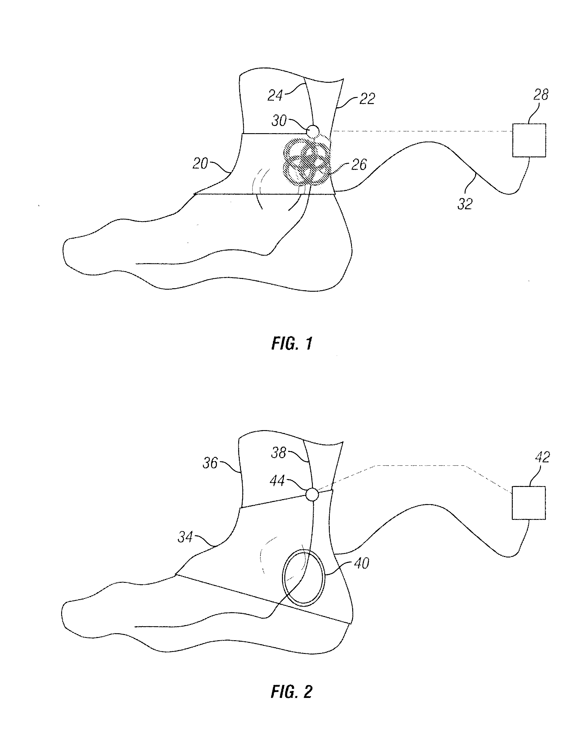
[0049]Referring first to FIG. 1, the invention includes a coil wrap 20, which is depicted as disposed over ankle 22 circumferentially to surround a portion of tibial nerve 24. Because tibial nerve 24 is targeted, this embodiment is particularly suited for the treatment of OAB and UI. In other embodiments of the invention, coil wrap 20 may be configured to surround other body parts that contain a portion of tibial nerve 24 or of other nerves branching from or connected to tibial nerve 24, still making these embodiments suitable for treating OAB and UI. In still other embodiments of the invention, coil wrap 20 may be configured for surrounding body parts that contain other nerves when treatments of other ailments are intended.

[0050]Coil wrap 20 may be manufactured from a variety of materials suitable for wearing over ankle 22. Preferably, coil wrap is produced from a soft, body-compatible material, natural or synthetic, for example, cotton, wool, polyester, rayon, Gore-Tex , or other ...

third embodiment

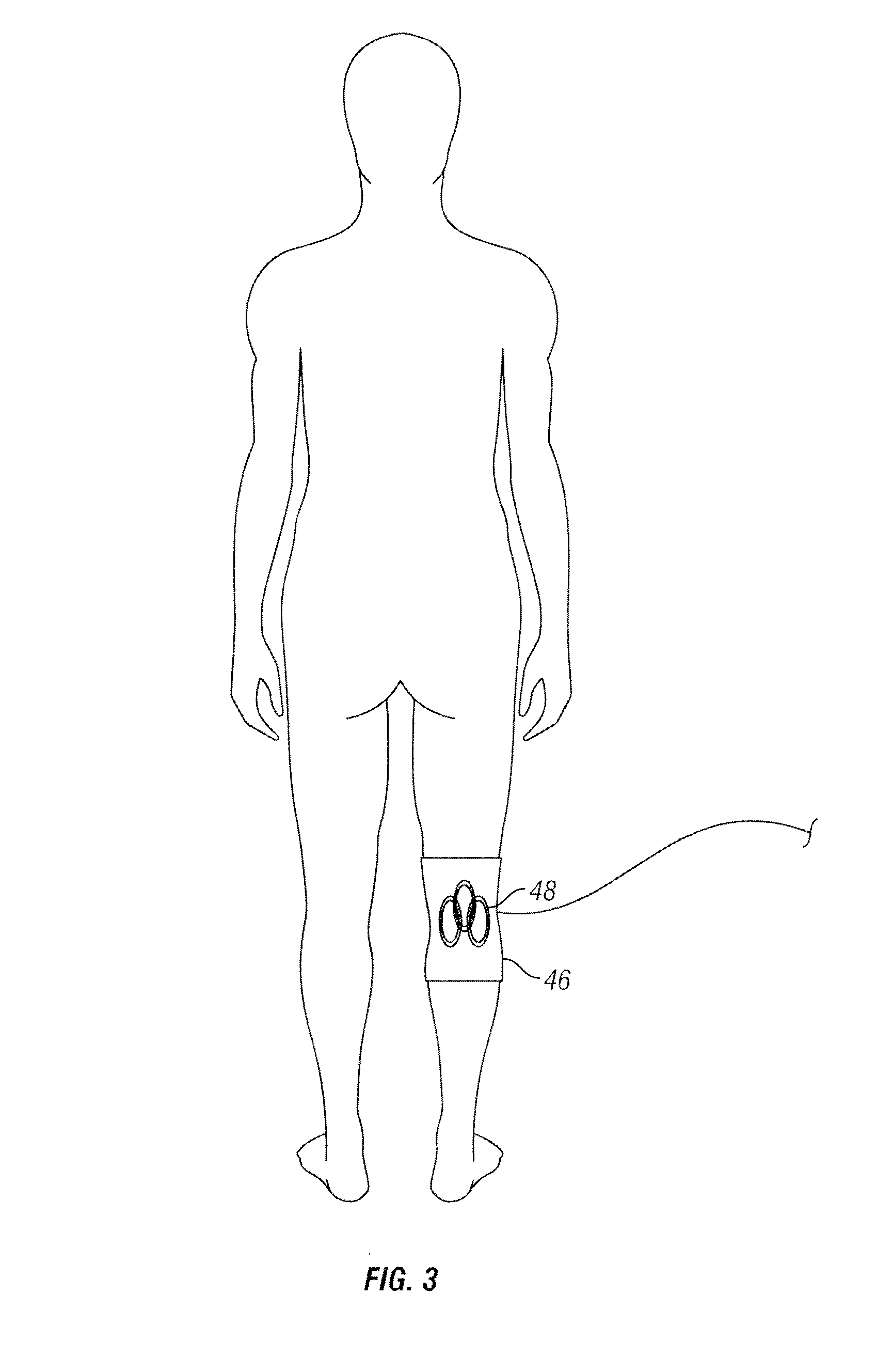
[0063]Referring now to FIG. 3, the invention includes a coil wrap 46 configured for wrapping over the popliteal fossa of a patient, in the region of the knee, to stimulate the posterior tibial nerve (not shown). The configuration and structure of coil wrap 46 reflect the body portion covered by coil wrap 46, but the key system components of coil wrap 46, such as the type, number and disposition of the coils (for example, the use of overlapping coils); the connections of the coils with a logic controller; and the use of one or more sensors (also not shown) to detect nerve conduction are all comparable to those in the previously described embodiments.

fourth embodiment

[0064]Referring now to FIG. 4, the invention includes a footrest or foot cradle 48, which is structured to contain at least a portion of a foot 50. One or more coils 52 are enclosed within cradle 48, and a sensor 54 is disposed along the pathway of tibial nerve 55, sensing conduction in tibial nerve 55, and is also connected to a logic controller 56. Coils 52, sensor 54 and logic controller 56 may be arranged in different configurations, in the same manner as in the preceding embodiments.

[0065]Cradle 48 may be made from a variety of materials and may be monolithic, or have a hollow or semi-hollow structure to enable the movement of coils 52 within cradle 48, as described in greater detail below. Preferably, cradle 48 has an ergonomically design allowing the ankle and heel of the patient to be retained within cradle 48, in a position that matches the positions of stimulating coils 52 to the area of stimulation. The design of cradle 48 provides for a particularly comfortable delivery ...


PUM


Abstract

An energy emitting apparatus for providing a medical therapy includes one or more energy generators, a logic controller electrically connected to the one or more energy generators, and one or more sensors for detecting electric conduction in a target nerve that are connected to the logic controller. The one or more energy generators produce energy focused on the target nerve upon receiving a signal from the logic controller, and the energy is varied by the logic controller according to an input provided by the one or more sensors. In one embodiment, the energy emitting apparatus is an apparatus for magnetic induction therapy that includes one or more conductive coils disposed in an ergonomic housing that produce a magnetic field focused on the target nerve upon receiving an electric current from the logic controller based on an input provided by the one or more sensors.

Description

CROSS-REFERENCE TO RELATED APPLICATIONS[0001]The present application claims priority to U.S. Provisional Patent Application Ser. No. 60 / 848,720, filed on Oct. 2, 2006 and titled: “Method and Apparatus for Magnetic Induction Therapy.”FIELD OF THE INVENTION[0002]The present invention relates to energy emitting apparatus and methods for providing a medical therapy. In one embodiment, the energy emitting apparatus is an ergonomic wrap or cradle that contains conductive coils generating a magnetic field directed to a target nerve.BACKGROUND OF THE INVENTION[0003]Overactive bladder (“OAB”) and urinary incontinence (“UI”) affect over 16% of the American population each year, or approximately 34 million men and women. Outside of the United States, OAB and UI affects over 46 million Europeans. The economic cost of OAB and UI is estimated to be in excess of $12 billion a year in the United States alone.[0004]Due to the social stigmas attached to OAB and UI and to misunderstandings related to ...

Claims


Application Information

Patent Timeline
IPC IPC(8): A61N2/02
CPCA61N1/08A61N2/02A61N2/006A61N1/3603
Inventor BURNETT, DANIEL R.HERMANSON, CHRISTOPHER
Owner EMKINETICS
Why Eureka
Try Eureka