Intravital-information imaging apparatus

a technology of intravenous information and imaging apparatus, which is applied in the field of intravenous information imaging apparatus, can solve the problems of difficult to accurately identify the constituents of biological tissues or measure density, and difficult to estimate the local amount of light with which the light absorber is irradiated,

Inactive Publication Date: 2008-12-11
CANON KK
View PDF2 Cites 61 Cited by
  • Summary
  • Abstract
  • Description
  • Claims
  • Application Information

AI Technical Summary

Benefits of technology

[0014]The present invention provides an intravital-information imaging apparatus with which it is possible to obtain a high-resolution distribution of optical chara

Problems solved by technology

However, since light introduced in a living body is diffused, it is difficult to estimate the local amount of light with which the light absorber is irradiated.
That is, it is difficult to calculate a distribution of the amounts of light with which the light absorber is irradiated (Φ) and to accurately separate and generate an im

Method used


Image

  • Intravital-information imaging apparatus
  • Intravital-information imaging apparatus
  • Intravital-information imaging apparatus

Examples


first embodiment

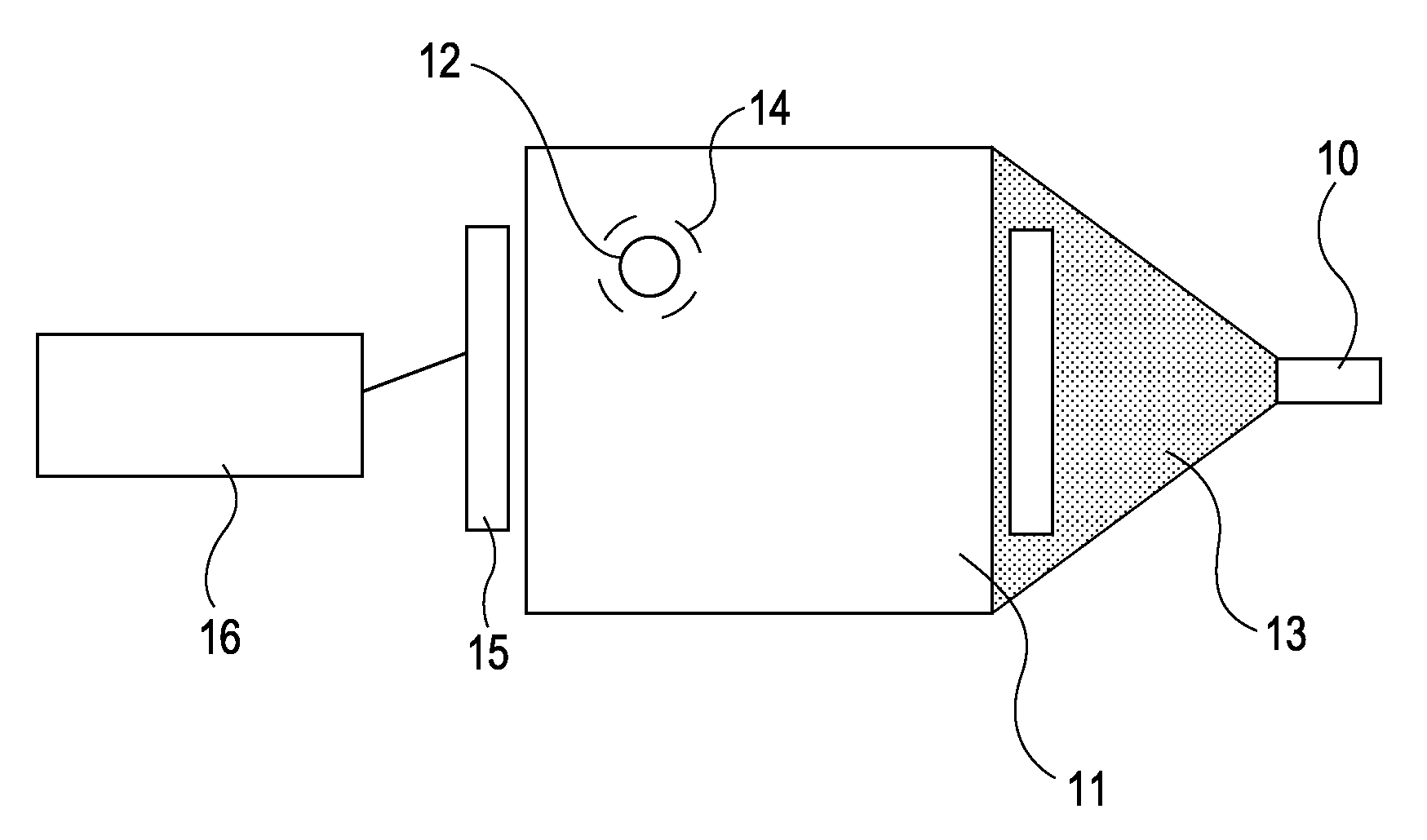
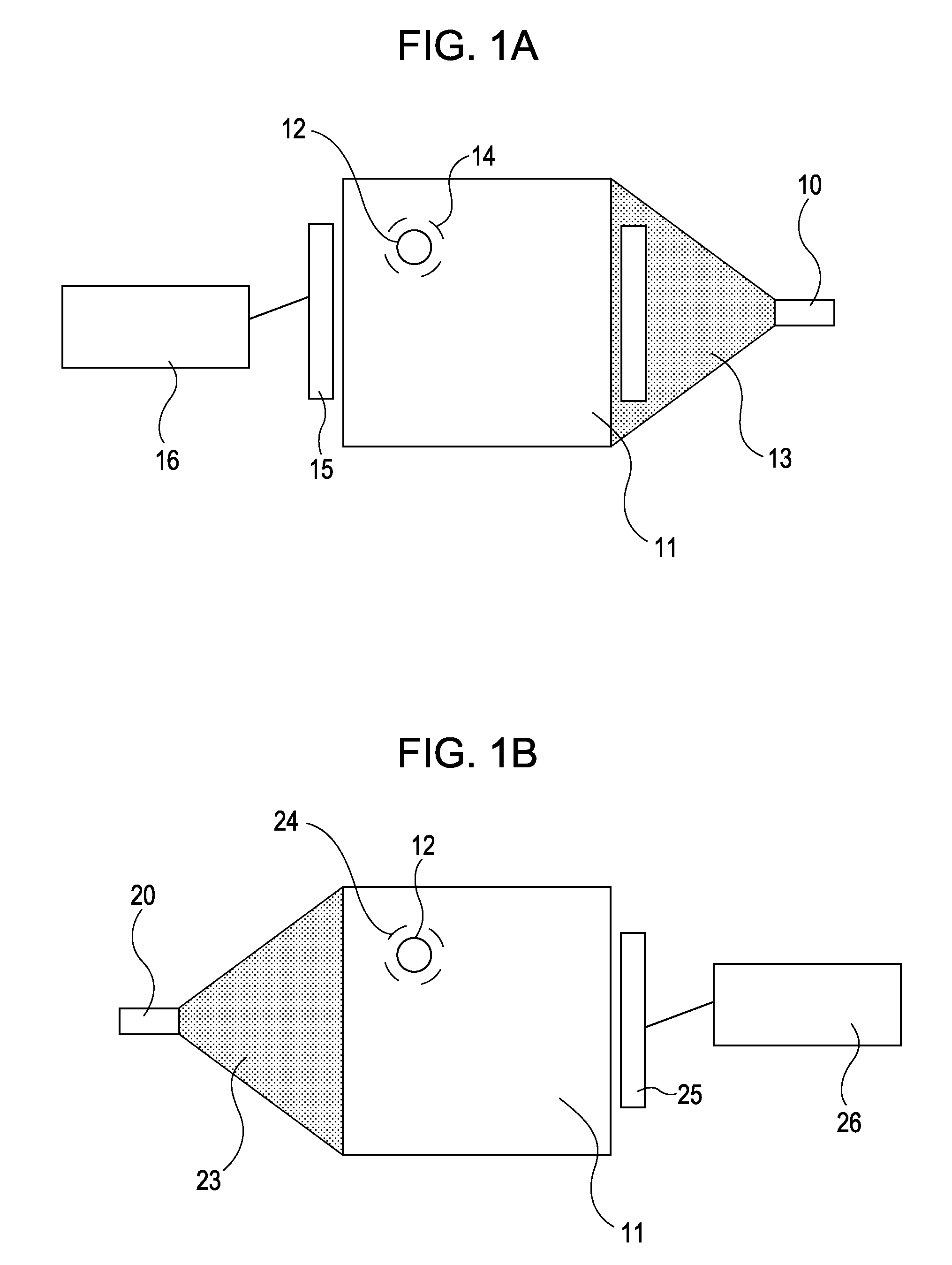
[0023]FIGS. 1A and 1B show an example of the configuration of an intravital-information imaging apparatus according to a first embodiment.

[0024]Referring to FIG. 1A, when a living body 11 is irradiated with pulsed light 13 from a first light source 10, an acoustic wave 14 is generated from a light absorber 12 inside the living body 11. The acoustic wave 14 is detected by an acoustic-wave detector 15 in the form of an electric signal. The detected electric signal is analyzed by a signal processor 16.

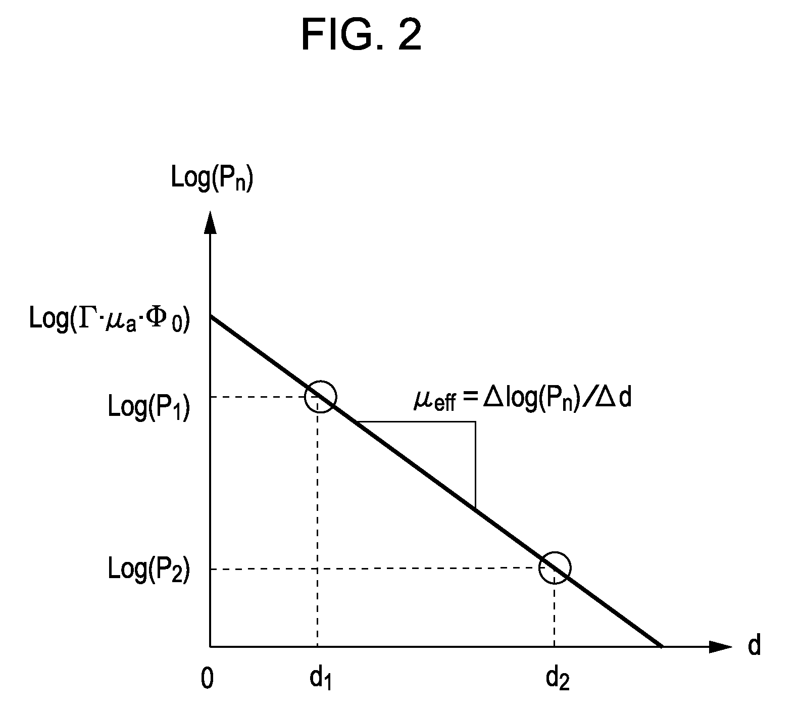
[0025]The initial sound pressure P1 of the acoustic wave 14 generated from the light absorber 12 in the living body 11 when the living body 11 is irradiated with the pulsed light 13 from the first light source 10 can be expressed by equation (2) below:

P1=Γ·μa·Φ=Γ·μa·Φ0·exp(−μeff·d1)   (2)

where Γ denotes the Grüneisen coefficient of the light absorber 12, μa denotes the absorption coefficient of the light absorber 12, Φ denotes the amount of local light absorbed by the light absorber 12, μ...

second embodiment

[0063]In a second embodiment, a distribution of optical characteristic values is calculated from information representing a temporal change in sound pressures, obtained by simultaneous irradiation by a plurality of light sources.

[0064]FIG. 3 shows an example of the configuration of an intravital-information imaging apparatus according to the second embodiment.

[0065]In FIG. 3, 30 denotes light sources, 31 denotes a living body, 32 denotes a light absorber, 33 denotes pulsed light, 34 denotes an acoustic wave, 35 denotes acoustic-wave detectors, and 36 denotes a signal processor (information processor).

[0066]When the living body 31 is irradiated with the pulsed light 33 spreading from the n (e.g., four in FIG. 3) light sources 30, the sound pressure Ptotal of the acoustic wave 34 generated from the light absorber 32 inside the living body 31 can be expressed by equation (6) below:

Ptotal=Γ·μa·Φ=Γ·μa·∑i=1nΦ0·exp(-μeff·di)(6)

where Γ denotes the Grüneisen coefficient of the light absorber...


PUM


Abstract

An intravital-information imaging apparatus includes light sources for irradiating a living body with light, and acoustic-wave detectors that detect acoustic waves generated from a light absorber having absorbed part of energy of the light from the light sources, the light absorber existing in the living body. Furthermore, the intravital-information imaging apparatus includes signal processors that calculate information representing a distribution of optical characteristic values of the living body using sound pressures of the acoustic waves generated from the light absorber.

Description

BACKGROUND OF THE INVENTION[0001]1. Field of the Invention[0002]The present invention relates to intravital-information imaging apparatuses.[0003]2. Description of the Related Art[0004]Generally, many imaging apparatuses that employ X-rays, ultrasound, or magnetic resonance imaging (MRI) are used in the medical field.[0005]Furthermore, in the medical field, research is being conducted for optical imaging apparatuses for obtaining intravital information by irradiating a living body with light from a light source, such as a laser, so that the light propagates in the living body, and detecting the propagated light or the like.[0006]As a type of optical imaging technique, photoacoustic tomography (PAT) has been proposed. Photoacoustic tomography is described, for example, in M. Xu and L. V. Wang, “Photoacoustic imaging in biomedicine”, Review of Scientific Instruments, 77, 041101 (2006).[0007]In photoacoustic tomography, a living body is irradiated with pulsed light emitted from a light...

Claims


Application Information

Patent Timeline
IPC IPC(8): A61B5/00
CPCA61B5/0059A61B5/0095A61B8/08G01N21/1702
Inventor FUKUTANI, KAZUHIKONAKAJIMA, TAKAONAGAE, KENICHISOMEDA, YASUHIROASAO, YASUFUMI
Owner CANON KK
Why Eureka
Try Eureka