Ultrasonic flow sensor with quadrature demodulation

Inactive Publication Date: 2008-12-18
ROBERT BOSCH GMBH
View PDF3 Cites 16 Cited by
  • Summary
  • Abstract
  • Description
  • Claims
  • Application Information

AI Technical Summary

Benefits of technology

[0008]The object of the present invention, therefore, is to increase the unambiguous range of the phase and transit time measurement of ultrasonic signals.
[0011]A further aspect of the present invention is to direct an ultrasonic signal that has been received to several parallel-connected quadrature demodulators that operate with different demodulation frequencies and each ascertain a piece of phase information about the ultrasonic signal that was received, and to direct the individual pieces of phase information to a vernier unit, which uses the information to calculate the phase angle (Δφ) of the ultrasonic signal with a larger unambiguous range. A zero phase of all demodulation frequencies is preferably used as the reference value for the phase determination. The advantage of determining several pieces of phase information from an ultrasonic signal and performing the evaluation using a vernier method is that the phase angle of the ultrasonic signal has a substantially larger unambiguous range than do known methods. As a result, an unambiguous range of, e.g., 150 μs or more may be attained.
[0012]The inventive evaluation unit preferably includes three or more quadrature demodulators. In principle, the quality of the measurement may be improved by using a larger number of quadrature demodulators. This also results in higher costs, however.
[0013]Within the framework of the quadrature demodulation, the ultrasonic signal is multiplied by the particular demodulation frequency and a demodulation signal that has been phase-shifted by 90°. The resultant signal corresponds to the real or imaginary part of the phase angle to be determined. A sinc filter is preferably located downstream of each of the quadrature demodulators. The sinc filters suppress the high-frequency interfering component of the real part and the imaginary part, e.g., noise.

Problems solved by technology

This therefore typically results in a relatively small unambiguous range.
Determining the remainder (n*2π) is often a very complex procedure.

Method used


Image

  • Ultrasonic flow sensor with quadrature demodulation
  • Ultrasonic flow sensor with quadrature demodulation
  • Ultrasonic flow sensor with quadrature demodulation

Examples


Embodiment Construction

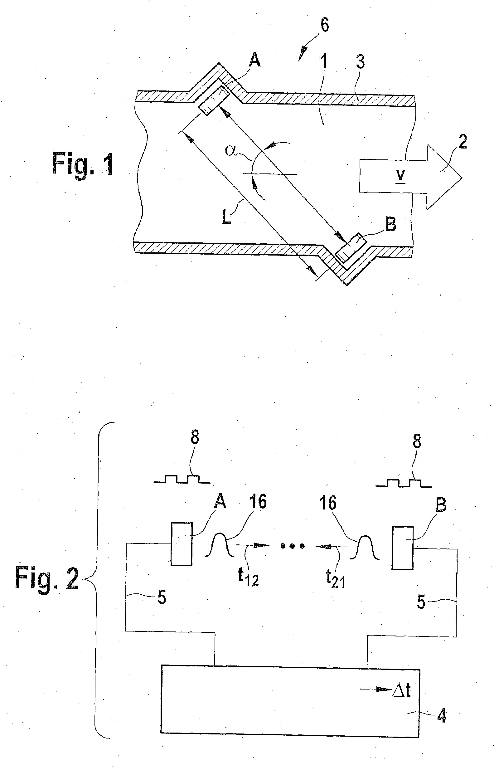
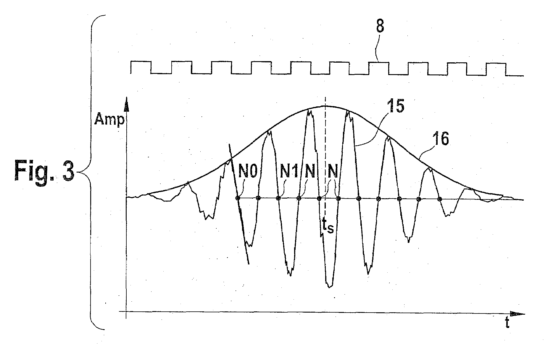
[0031]FIGS. 1 through 3 are explained in the introduction to the description,

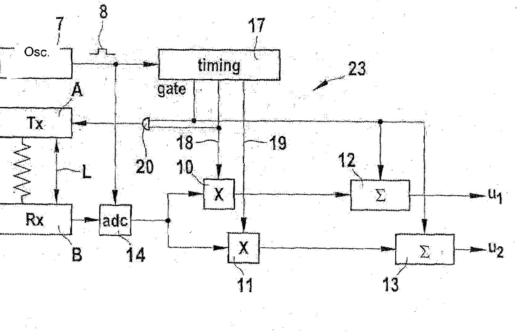
[0032]FIG. 4 shows a schematic overview of a system for measuring the phase and / or transit time of an ultrasonic signal 15. The system includes (from left to right) a sensor 26, such as a converter A or B, a demodulator unit 27 with several quadrature demodulators (see FIG. 5), an optional unit 28 for phase correction of signals delivered by demodulator unit 27, a CORDIC algorithm, which performs an arctangent calculation, and a vernier unit 30, which calculates phase angle φ and / or transit time t of ultrasonic signal 15 based on the individual phase angles α1-αn.

[0033]FIG. 5 shows the demodulator unit 27 of FIG. 4 in detail. Demodulator unit 27 includes an A / D converter 14, with which ultrasonic signal 15 that was received is digitized, and a plurality of parallel-connected quadrature demodulators 23a-23c, which process the digitized signal. The function of the quadrature demodulator is explained below in ...


PUM


Abstract

An ultrasonic flow sensor, in particular for determining the flow velocity of a medium flowing through a pipeline, has at least one ultrasonic converter for transmitting and / or receiving ultrasonic signals, an oscillator, which is connected with the ultrasonic converter, and an evaluation unit, which determines a phase shift of the ultrasonic signal that was received, with respect to a reference signal. The evaluation unit includes a plurality of quadrature demodulators, which operate with different demodulation frequencies and each determine phase information about the ultrasonic signal that was received, and when a vernier unit is provided, which determines—based on the individual pieces of phase information—a phase angle or a quantity proportional thereto.

Description

CROSS-REFERENCE TO A RELATED APPLICATION[0001]The invention described and claimed hereinbelow is also described in German Patent Application DE 10 2007 027188.5 filed on Jun. 16, 2007. This German Patent Application, whose subject matter is incorporated here by reference, provides the basis for a claim of priority of invention under 35 U.S.C. 119(a)-(d).BACKGROUND OF THE INVENTION[0002]The present invention relates to an ultrasonic flow sensor for determining the transit time of an ultrasonic signal, and to a related method.[0003]Ultrasonic flow sensors are used, in particular, to measure the volumetric flow, mass flow, or the flow velocity of a gaseous or liquid medium flowing through a pipeline or the like. A known type of ultrasonic flow sensor includes two ultrasonic converters located such that they are offset in the direction of flow, each of which generates ultrasonic signals and transmits them to the other ultrasonic converter. The ultrasonic signals are received by the othe...

Claims


Application Information

Patent Timeline
IPC IPC(8): G01F1/66
CPCG01F1/667
Inventor ZHANG, JIAWEIOPTIZ, BERNHARDHORSTBRINK, MICHAELLANG, TOBIASWENZLER, AXEL
Owner ROBERT BOSCH GMBH
Why Eureka
Try Eureka