Nevertheless, problems with the long-term
image quality of these displays have prevented their widespread usage.
For example, particles that make up electrophoretic displays tend to settle, resulting in inadequate service-life for these displays.
Such gas-based electrophoretic media appear to be susceptible to the same types of problems due to particle
settling as liquid-based electrophoretic media, when the media are used in an orientation which permits such
settling, for example in a sign where the medium is disposed in a
vertical plane.
Indeed, particle
settling appears to be a more serious problem in gas-based electrophoretic media than in liquid-based ones, since the lower
viscosity of gaseous suspending fluids as compared with liquid ones allows more rapid settling of the electrophoretic particles.
However, the methods used for assembling LCD's cannot be used with
solid electro-optic displays.
This LCD assembly process cannot readily be transferred to
solid electro-optic displays.
Electro-optic displays are often costly; for example, the cost of the color LCD found in a
portable computer is typically a substantial fraction of the entire cost of the computer.
However, this method of forming connections tends to be undesirable from a manufacturing point of view, since the placement of the connections is of course a function of the
backplane design, so that FPL coated with a specific arrangement of gutters can only be used with one, or a limited range of backplanes, whereas for economic reasons it is desirable to produce only one form of FPL which can be used with any
backplane.
However, such removal of electro-optic medium poses its own problems, especially when the FPL is formed by
coating a thin (less than about 25 μm) polymeric film.
Typically, the electro-optic medium must be removed by the use of solvents or mechanical cleaning, either of which may result in damage to, or removal of, the electrically-conductive layer of the FPL (this electrically-conductive layer usually being a layer of a
metal oxide, for example
indium tin oxide, less than 1 μm thick), causing a failed
electrical connection.
In extreme cases, damage may also be caused to the front substrate (typically a polymeric film) which is used to support and mechanically protect the conductive layer.
In some cases, the materials from which the electro-optic medium is formed may not be easily solvated, and it may not be possible to remove them without the use of aggressive solvents and / or high mechanical pressures, either of which will exacerbate the aforementioned problems.
Also, depending upon the location of the connection, bending of the electrically-conductive layer and the associated front substrate may crack the conductive layer, resulting in failure to make a proper connection between the
backplane and the conductive layer, and hence display failure.
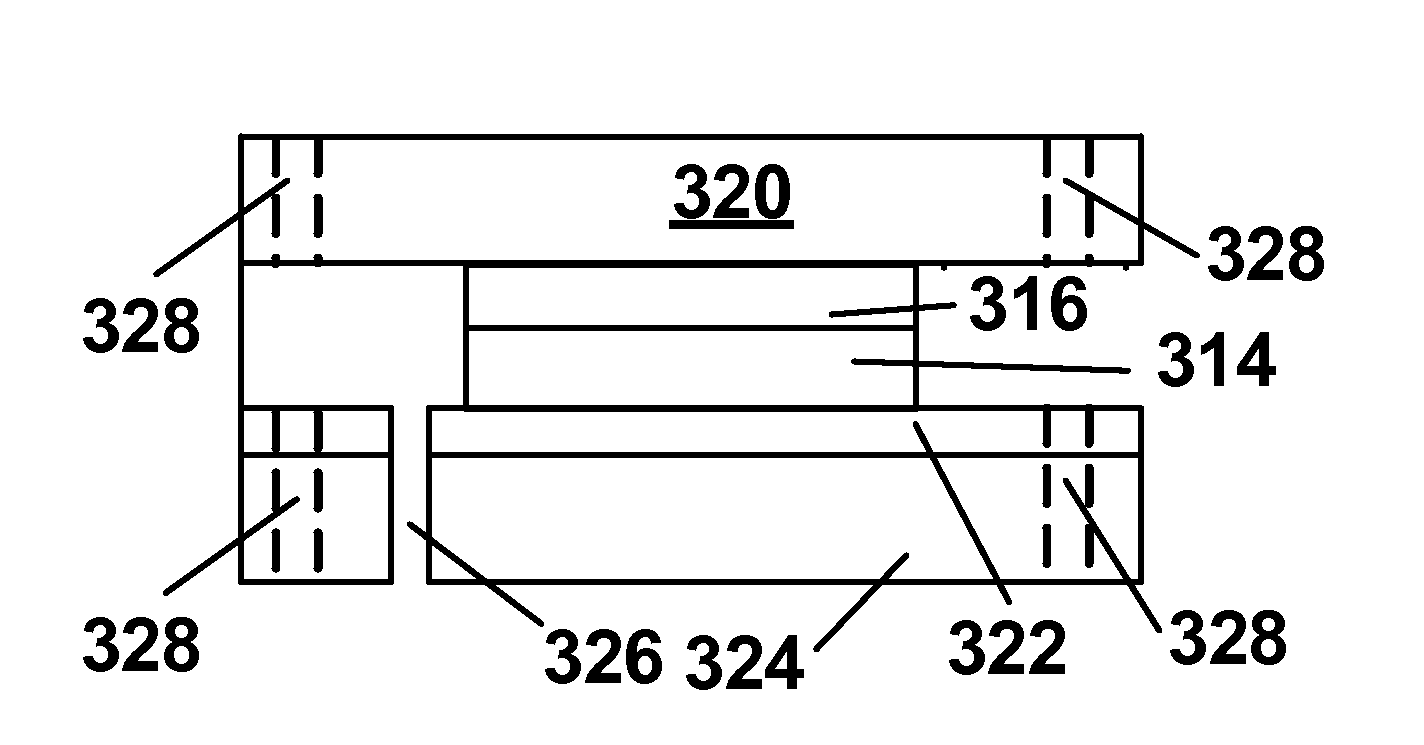
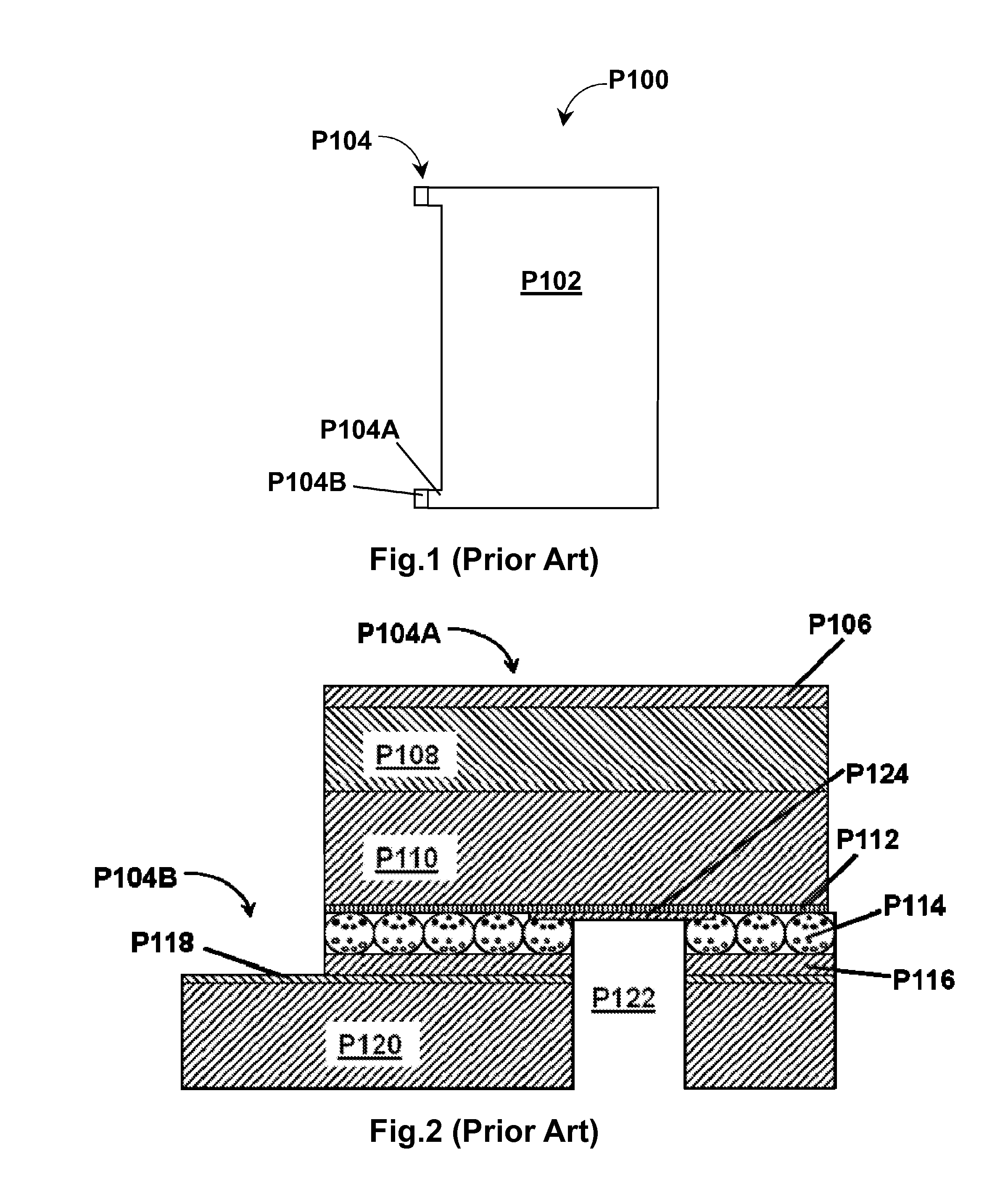
However, when the prior art FPL structure shown in FIGS. 1 and 2 is based upon a PET layer having a thickness of about 1 mil (25 μm), there is a risk of mechanical damage to the aperture P122 or the adjacent parts of the silver layer P124 and ITO layer P112, and since in this structure the apertures P122 are used both for testing purposes and as the top plane connections in the final display, any damage to the apertures or the adjacent conductive
layers during testing may affect the performance of the final display.
Such
laser cutting may damage the silver layer P124 and / or the adjacent part of the ITO layer P112, with the disadvantageous results already noted.
Moreover, the structure shown in FIGS. 1 and 2 requires that the same top plane connections (apertures P122) be used for both testing and in the final display, whereas for
engineering reasons it may be more convenient to provide separate sets of top plane connections for the two purposes, and leaves the inner tab sections P104A remaining on the final FPL after the conductive release sheet P118 / P120 has been removed, and in some cases the presence of these protruding inner tab sections P104A may be inconvenient.

