Liquid crystal display and method of testing the same

a liquid crystal display and display panel technology, applied in the field of failure detection and testing of liquid crystal display devices, can solve the problems of easy detection of failure state not impossible to detect some failures of gate drivers, and failure of liquid crystal display panels

Active Publication Date: 2008-12-18
LG DISPLAY CO LTD
View PDF5 Cites 18 Cited by
  • Summary
  • Abstract
  • Description
  • Claims
  • Application Information

AI Technical Summary

Benefits of technology

[0013]An advantage of the present invention is to provide a liquid crystal display that is capable of detecting a failure of a gate driver, and a method of testing the same.
[0014]Additional advantages and features of the invention will be set forth in part in the description which follows and in part will become apparent to those having ordinary skill in the art upon examination of the following or may be learned from practice of the invention. These and other advantages of the invention may be realized and attained by the structure particularly pointed out in the written description and claims hereof as well as the appended drawings.
[0015]To achieve these and other advantages and in accordance with the purpose of the invention, as embodied and broadly described herein, a liquid crystal display includes a liquid crystal display panel on which liquid crystal cells connected to thin film transistors (TFTs) located at crossings between gate lines and data lines are formed; a data driver that drives the data lines of the liquid crystal display panel; and a gate driver that includes first to nth stages (n is a natural number larger than 1) formed on the liquid crystal display panel, generates normal scan signals for turning on the TFTs in a normal mode, and generates test scan signals for turning off the TFTs in a test mode.
[0016]In another aspect of the present invention, there is provided a method of testing a liquid crystal display including a liquid crystal display panel on which liquid crystal cells connected to thin film transistors (TFTs) located at crossings between gate lines and data lines are formed, the method including: sequentially test scan signals for turning off the TFTs, that are generated by a gate driver including first to nth stages formed on the liquid crystal display panel, to the gate lines of the liquid crystal display panel; supplying pixel voltage signals to the data lines of the liquid crystal display panel; and determining whether or not images corresponding to the pixel voltage signals are displayed on the liquid crystal display panel.
[0017]It is to be understood that both the foregoing general description and the following detailed description of the present invention are exemplary and explanatory and are intended to provide further explanation of the invention as claimed.

Problems solved by technology

In the testing process, the TFT is turned on in response to a scan signal generated by the gate driver and a test pixel signal is supplied from the data line to the liquid crystal cell via the TFT, such that a failure of the liquid crystal display panel is detected.
When a failure occurs in a signal line of the liquid crystal display panel, a pixel connected to the signal line displays an image different from a pixel connected to a normal signal line and accordingly a failure state of the liquid crystal display panel can be easily detected.
However, using the related art methods of testing the liquid crystal display, it is not impossible to detect some failures of the gate driver that may occur while the gate driver is manufactured.
That is, when a failure occurs in the gate driver, the gate driver may abnormally operate to output a scan signal having an abnormal level instead of a normal level the failure may not be detected.
In the liquid crystal display panel that is determined to be good in spite of having a scan signal having the abnormal level, a failure phenomenon may occur in a driving environment or upon application of a specific driving pattern.
The failure phenomenon may gradually become more serious so that a defect becomes visible to a user after the elapse of the time.

Method used


Image

  • Liquid crystal display and method of testing the same
  • Liquid crystal display and method of testing the same
  • Liquid crystal display and method of testing the same

Examples


Embodiment Construction

[0027]Reference will now be made in detail to the embodiments of the present invention, examples of which are illustrated in the accompanying drawings. Wherever possible, the same reference numbers will be used throughout the drawings to refer to the same or like parts.

[0028]Hereinafter, exemplary embodiments of the present invention will be described with reference to FIGS. 1 to 6.

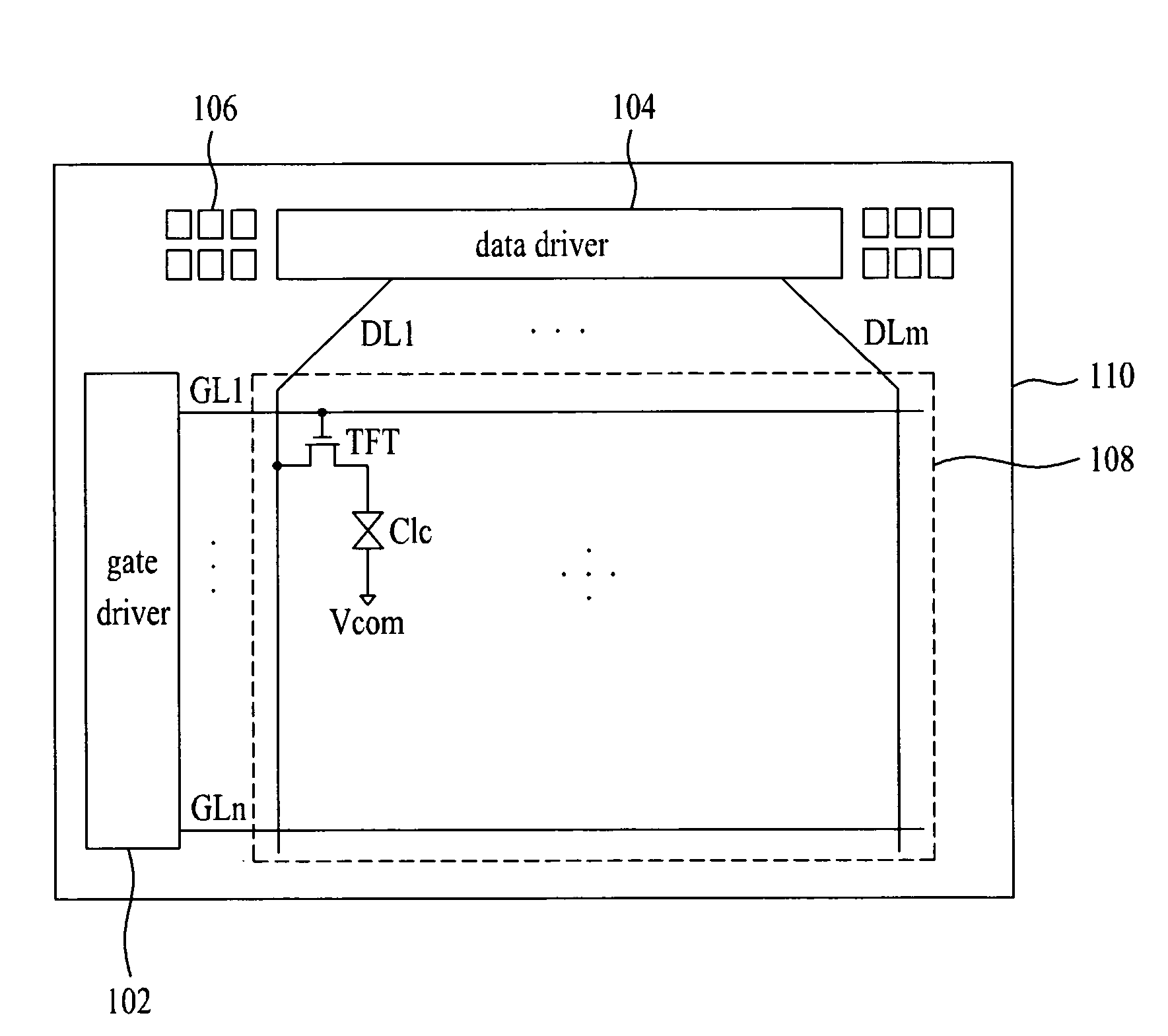
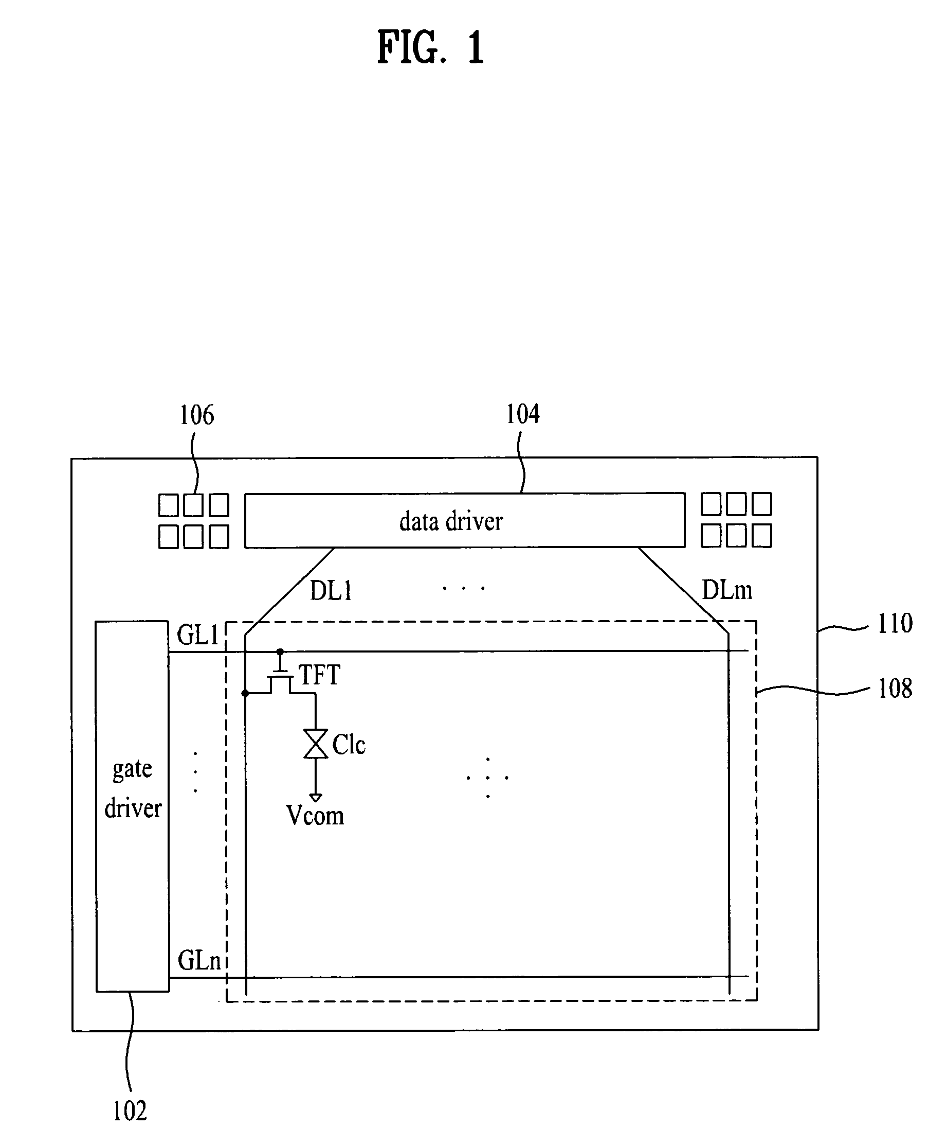
[0029]FIG. 1 is a block diagram showing a liquid crystal display according to the present invention.

[0030]Referring to FIG. 1, the liquid crystal display according to the present invention includes a liquid crystal display panel 110 having an image display unit 108, a data driver for driving data lines DL of the image display unit 108, and a gate driver 102 for driving gate lines GL of the image display unit 108.

[0031]The data driver 104 generates pixel data signals for one horizontal line in every horizontal period in response to data control signals from a timing controller. In particular, the data driv...


PUM


Abstract

A liquid crystal display is capable of detecting a failure of a gate driver, and a method of testing the same are provided. The liquid crystal display includes a liquid crystal display panel on which liquid crystal cells connected to thin film transistors (TFTs) located at crossings between gate lines and data lines are formed, a data driver that drives the data lines of the liquid crystal display panel, and a gate driver which includes first to nth stages (n is a natural number larger than 1) formed on the liquid crystal display panel that generates normal scan signals for turning on the TFTs in a normal mode, and that generates test scan signals for turning off the TFTs in a test mode.

Description

[0001]This application claims the benefit of Korean Patent Application No. 2007-057069, filed on Jun. 12, 2007, which is hereby incorporated by reference for all purposes as if fully set forth herein.BACKGROUND OF THE INVENTION[0002]1. Field of the Invention[0003]The present invention relates to liquid crystal display devices and more particularly to failure detection and testing of a liquid crystal display.[0004]2. Discussion of the Related Art[0005]Generally, a liquid crystal display (LCD) displays an image by adjusting light transmission of liquid crystal cells arranged in a matrix on a liquid crystal display panel according to video signals.[0006]The liquid crystal display panel includes a thin film transistor (TFT) substrate and a color filter substrate bonded together by a sealant with liquid crystal interposed therebetween.[0007]In the color filter substrate, a color filter array including a black matrix for preventing light leakage, a color filter for realizing color, a comm...

Claims


Application Information

Patent Timeline
Patent Type & Authority Applications(United States)
IPC IPC(8): G09G3/36G01R31/28
CPCG09G3/006G09G3/3648G02F1/13G02F1/133
Inventor JANG, CHANG JAEKONG, CHUNG SIK
Owner LG DISPLAY CO LTD
Why Eureka
Try Eureka