Electronic control unit with expanded blocks

a control unit and expanded block technology, applied in the direction of electrical apparatus, electrical device contruction details, coupling device connections, etc., can solve the problems of high mechanical inertia, large-sized electric/electronic components (i.e. electrolytic capacitors) are particularly prone to mechanical stresses, and mechanical solutions described above, while being effective, and achieves cost-effective manufacturing. , the effect of easy and cost-effectiv

Inactive Publication Date: 2008-12-18
FAB ITAL MAGNETI MARELLI SPA
View PDF14 Cites 26 Cited by
  • Summary
  • Abstract
  • Description
  • Claims
  • Application Information

AI Technical Summary

Benefits of technology

[0008]It is the object of the present invention to make an electronic control unit which is free from the above-described drawbacks and is specifically easy and cost-effective to manufacture.

Problems solved by technology

It has been observed that large-sized electric / electronic components (i.e. electrolytic capacitors) are particularly prone to mechanical stresses, because they are only inferiorly fixed (welded) to the printed circuit board and present a heavy mass (and thus a high mechanical inertia) having a centre of gravity relatively distant from the printed circuit board.
The mechanical solutions described above, however, while being effective are costly because they require additional, highly automated machining operations.
Patents DE2823666A1 and U.S. Pat. No. 6,123,565 A1 describe an electronic control unit for automotive applications, wherein the housing is completely filled with an expanded foam to limit the vibrations which are transmitted to the electric / electronic components; however, this constructive solution implies various drawbacks because it is costly, difficult to implement and makes any repair intervention on the electronic control unit extremely complicated.

Method used


Image

  • Electronic control unit with expanded blocks
  • Electronic control unit with expanded blocks
  • Electronic control unit with expanded blocks

Examples


Embodiment Construction

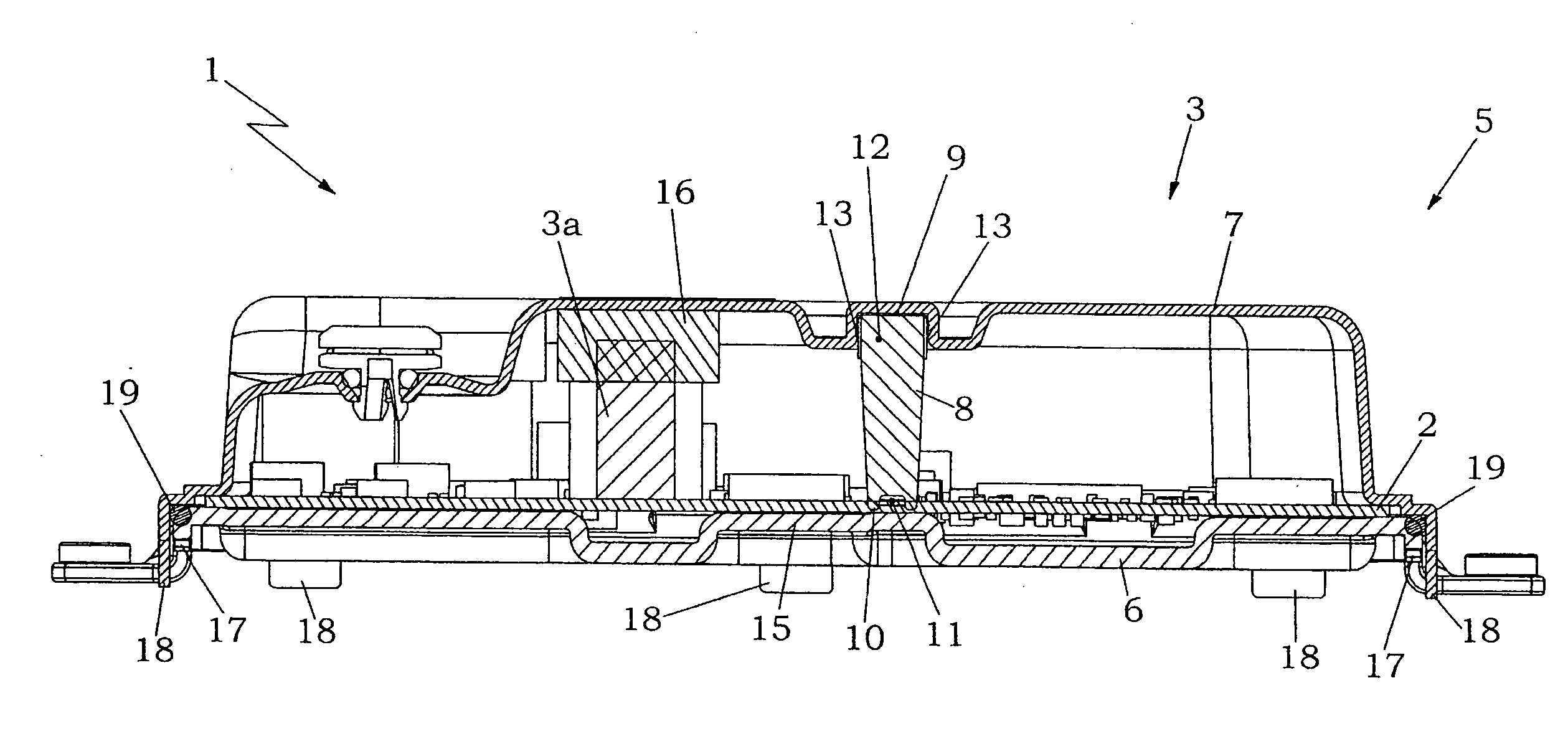
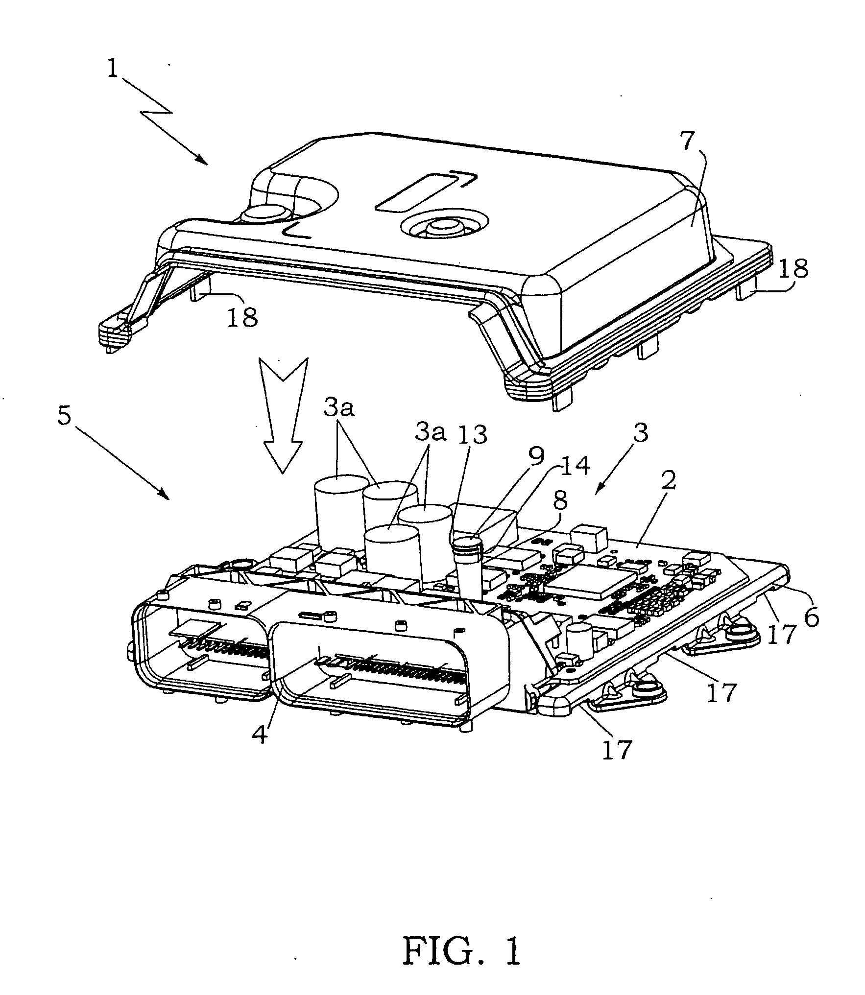
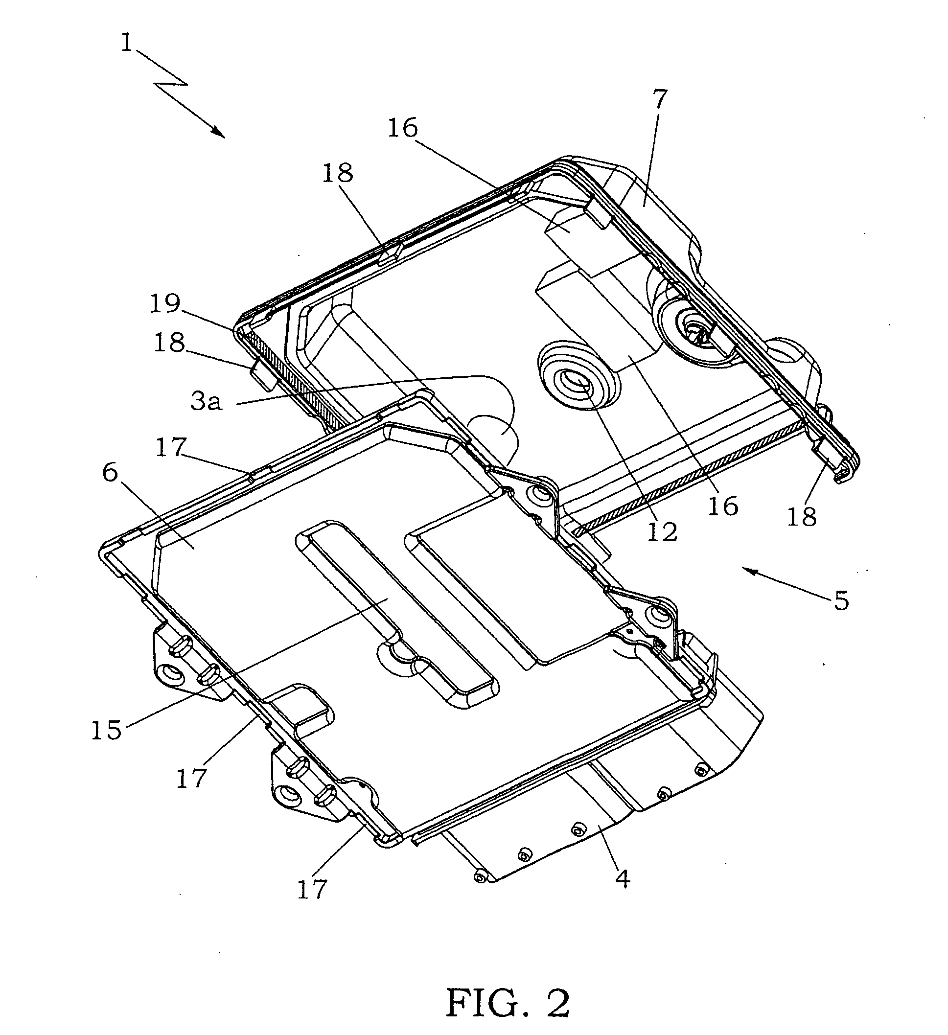
[0016]In FIG. 1, numeral 1 indicates as a whole an electronic control unit for an internal combustion engine.

[0017]Electronic control unit 1 comprises a printed circuit board 2, which supports an electric circuit, a plurality of electric / electronic components 3 electrically connected to the electric circuit, and a connector 4 electrically connected to the electric circuit to connect electronic control unit 1 to the internal combustion engine wiring. Specifically, printed circuit board 2 supports four electrolytic capacitors 3a, which have a cylindrical shape and present large dimensions and a heavy mass.

[0018]Furthermore, electronic control unit 1 comprises a housing 5, which presents a rectangular shape in plan, accommodates therein printed circuit board 2 and comprises a base 6 which inferiorly supports printed circuit board 2 and a lid 7 which superiorly closes base 6. In addition to its natural containing and mechanical protection function, base 6 of housing 5 performs the funct...


PUM


Abstract

An electronic control unit presenting: a printed circuit board, which supports an electric circuit, a plurality of electric / electronic components electrically connected to the electric circuit, and at least one connector electrically connected to the electrical circuit; a housing, which accommodates therein the printed circuit board and comprises a base which inferiorly supports the printed circuit board and a lid which superiorly closes the base; and at least one deformable, elastic, expanded blocking block, which is fixed to an internal surface of the lid near at least one electric / electronic component, presents a sufficient thickness so as to determine a vertical interference with the first electric / electronic component to be compressed between the lid and the first electric / electronic component, and presents a larger area than the first electric / electronic component to laterally encompass the first electric / electronic component.

Description

[0001]The present invention relates to an electronic control unit.[0002]The present invention finds advantageous application in an electronic control unit of an internal combustion engine, to which explicit reference will be made in the following description without because of this loosing in generality.BACKGROUND OF THE INVENTION[0003]An electronic control unit for an internal combustion engine comprises a PCB (Printed Circuit Board), which supports an electronic circuit, a plurality of electric / electronic components electrically connected to the electric circuit, and at least one connector electrically connected to the electric circuit for connecting the electronic control unit to the internal combustion engine wiring. The printed circuit board is accommodated in a housing, which comprises a base which inferiorly supports the printed circuit board and a lid which superiorly closes the base.[0004]An electronic control unit for an internal combustion engine is normally arranged insi...

Claims


Application Information

Patent Timeline
Patent Type & Authority Applications(United States)
IPC IPC(8): H05K5/00
CPCH05K7/20454H05K7/20854
Inventor FINO, ENDRIOCICOGNATI, FULVIO
Owner FAB ITAL MAGNETI MARELLI SPA
Why Eureka
Try Eureka