
Lubricating formulations for dispersancy and temperature, friction, and wear reduction

a technology of dispersant and temperature, friction, wear reduction, applied in the direction of additives, liquid carbonaceous fuels, base materials, etc., can solve the problems of high corrosiveness of additives and unsuitable for a number of uses, and achieve the effect of reducing the gas consumption of these cars

Inactive Publication Date: 2008-12-18
LYON DEV
View PDF33 Cites 14 Cited by
  • Summary
  • Abstract
  • Description
  • Claims
  • Application Information

AI Technical Summary

Benefits of technology

[0092]Hydrodynamic Lubrication—When a viscous film completely separates moving surfaces. It is affected solely by the ‘pumping’ action developed by the sliding of one surface over another in contact with lubricating oil. Adhesion to the moving surface draws the oil into a high-pressure wedge shape area between the surfaces, and viscosity retards the tendency to squeeze the oil out.
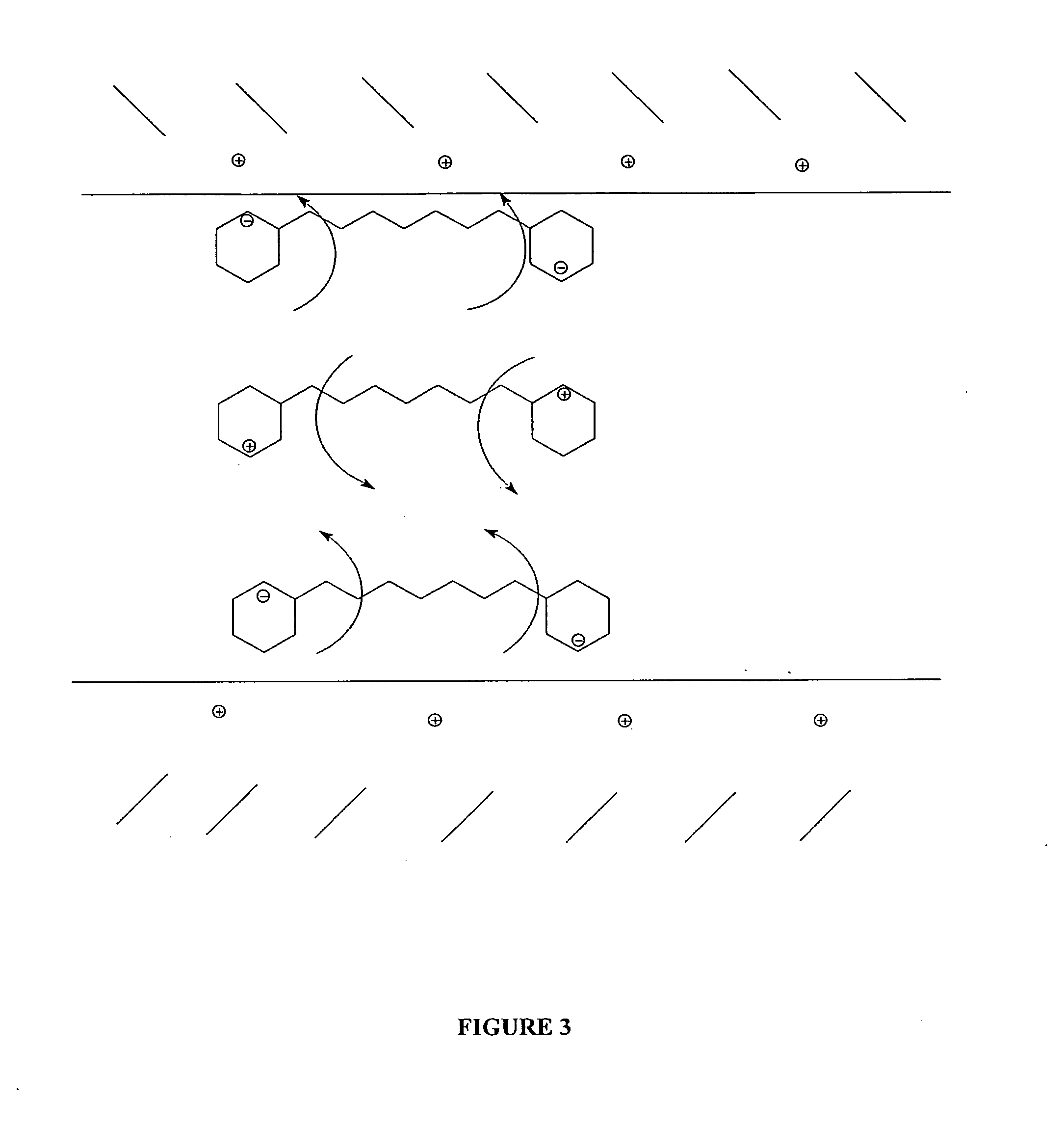
[0116]In accordance with one aspect of the present invention, the combination of polar materials increases a boundary layer without increasing the viscosity of an associated oil or working fluid.

Problems solved by technology

Such additives are highly corrosive, however, and for that reason are not suitable for a number of uses, such as in the lubrication of internal combustion engines.

Method used


Image

  • Lubricating formulations for dispersancy and temperature, friction, and wear reduction
  • Lubricating formulations for dispersancy and temperature, friction, and wear reduction
  • Lubricating formulations for dispersancy and temperature, friction, and wear reduction

Examples


experiment 1

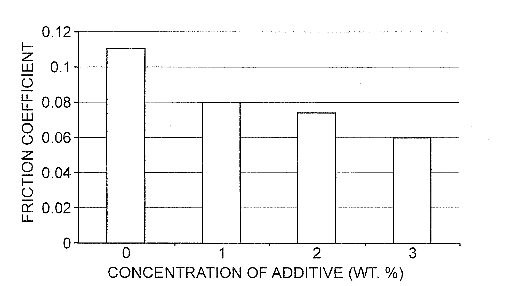
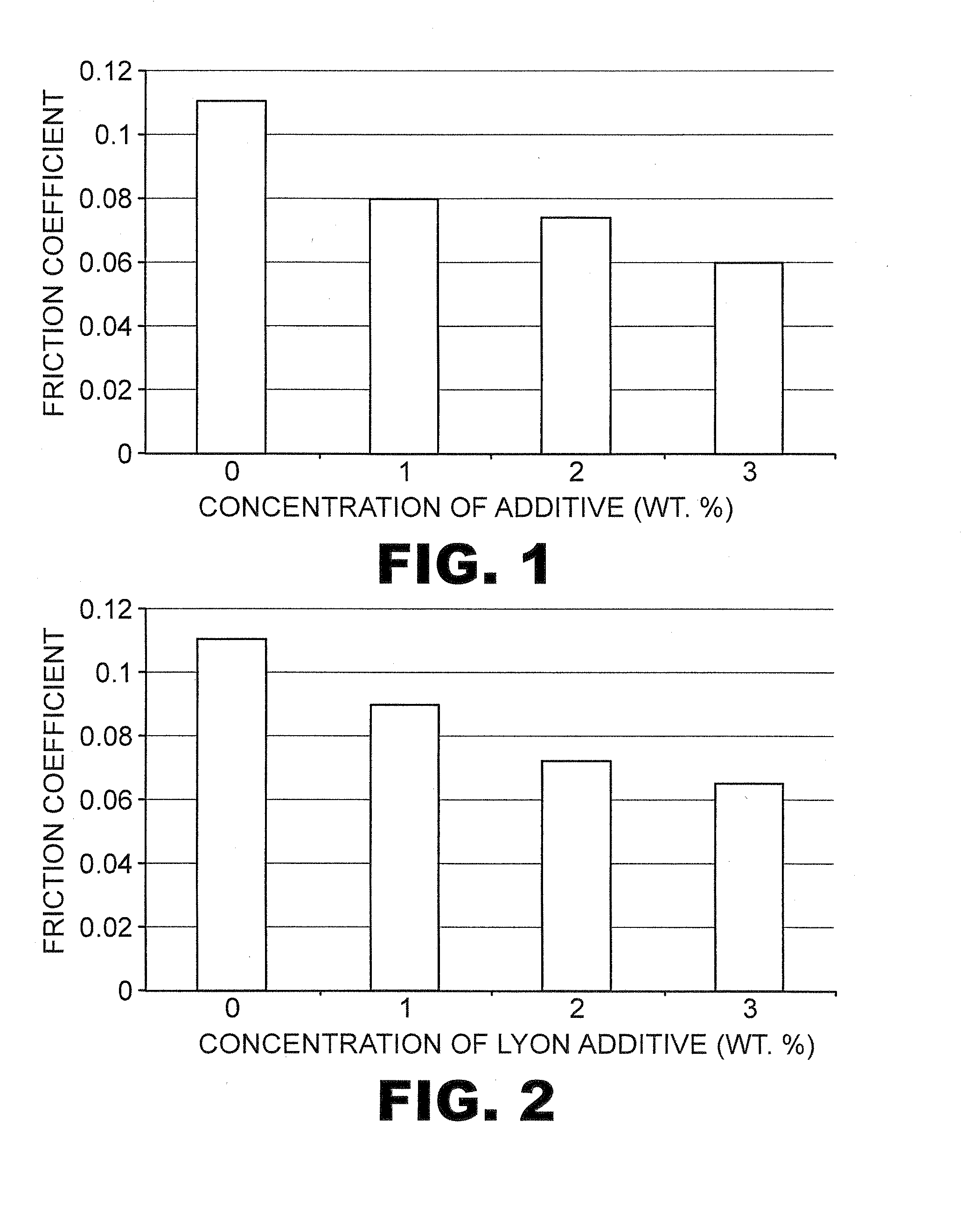
[0185]Initially, a control and a first sample, embodying the technology of the present invention, were subjected to the modified McMillan test. The control included a conventional, petroleum based 5W-30 motor oil (BP); the sample embodying the present invention included the same motor oil and an additive package consisting of a 1.5 percent concentration by weight of the overall composition. Results are shown in Table 1.

TABLE 1Coef. Of FrictionWear RateControl 10.102.5 × 10−6 mm3 / NmSample 10.0671.0 × 10−8 mm3 / Nm

experiment 2

[0186]Compositions identical to control 1 and sample 1 were subjected to ASTM D 2670 (modified) by Falex Corporation. This data is presented in Table 2.

TABLE 2Final oilBreak-intemperaturetooth lossTest tooth lossFriction factor(° F.)Control 150480.12235Sample 1870.08157

[0187]The Falex test apparatus placed a rotating cylinder between V-blocks in a container filled with the fluid being tested. The test was run in 2 phases, i.e., a break in period of one minute, wherein the cylinder works in uniformly between the V-blocks, followed by a three hour test where the wear, temperature, and torque are monitored. The tooth loss is an indication of the wear and the friction factor is computed from the friction and applied forces.

experiment 3

[0188]A master batch composed of 95 to 100 wt % working fluid (Mobil Super Syn 5W-20) and 0.1 to 5 wt % working fluid additive including: 1 to 100 wt % of an highly polar primary component, 0.4 to 95 wt % of a highly polar secondary material, and 0.02 to 20% organometallic material. The results are presented in Table 3.

TABLE 3Friction factorWear scarControl (neat)0.0940.75Test sample0.0730.60


PUM


Abstract

The present invention provides a working fluid additive for use in conjunction with a working fluid within an operating system having contact surfaces. The working fluid additive may consist solely of a highly polar material, but preferably includes both a highly polar material and a material that is synergistic to the highly polar material. The highly polar materials have a great affinity for the contact surfaces within the operating system and, therefore, produce film layers on the contact surfaces sufficient to significantly eliminate the frictional losses experience in the boundary regime of lubrication. By including a synergistic polar material, the efficacy as well as the thickness of this film layer is increased to further increase friction reduction. Organo-metallics may be utilized to further decrease wear and friction. An enhancing accelerator may be used to increase the compatibility between the host working fluid and the additive. A dispersion agent may also be employed within to disperse the working fluid additive within the working fluid.

Description

[0001]This application is a continuation-in-part of U.S. Ser. No. 10 / 914,568, entitled ADDITIVES FOR LUBRICATING COMPOSITIONS, filed Aug. 9, 2004, and also claims priority to U.S. Ser. No. 60 / 792,280, entitled LUBRICATING FORMULATIONS FOR DISPERSANCY AND TEMPERATURE, FRICTION, AND WEAR REDUCTION, filed Apr. 14, 2006. Lubricating materials and additives are provided which form low friction, anti-wear, dispersant, corrosion free lubricating compositions.I. Field of the Invention[0002]The present invention relates to unique compositions for lubricating metals.A. BACKGROUND OF THE INVENTION[0003]When two similar or dissimilar surfaces rub together, progressive loss of material from the operating surfaces may occur. This loss of material, or wear, is accelerated by elevated temperatures and pressures which, for example, occur in internal combustion engines, hypoid gears, transmissions, industrial machines, propulsion engines, wheel bearings, gear oils, turbine oils, cutting fluids, instr...

Claims


Application Information

Patent Timeline
IPC IPC(8): C10M125/26C10M135/36C10M133/48
CPCC10M141/02C10M2207/123C10M2207/28
Inventor ROUNTREE, PHILIP L.LUTHERN, JOHN J.
Owner LYON DEV
Learn More