Angular adjusting mechanism for use in massage device of massage machine

Active Publication Date: 2008-12-18
CHEN KO PO
View PDF4 Cites 3 Cited by
  • Summary
  • Abstract
  • Description
  • Claims
  • Application Information

AI Technical Summary

Benefits of technology

[0008]The primary object of the present invention is to provide an angular adjusting mechanism for use in a massage device of a massage machine that during the rotation of a screw, the screw ma

Problems solved by technology

However, in the engagement status of the worm 34 and the worm gear 35, the

Method used


Image

  • Angular adjusting mechanism for use in massage device of massage machine
  • Angular adjusting mechanism for use in massage device of massage machine
  • Angular adjusting mechanism for use in massage device of massage machine

Examples


Embodiment Construction

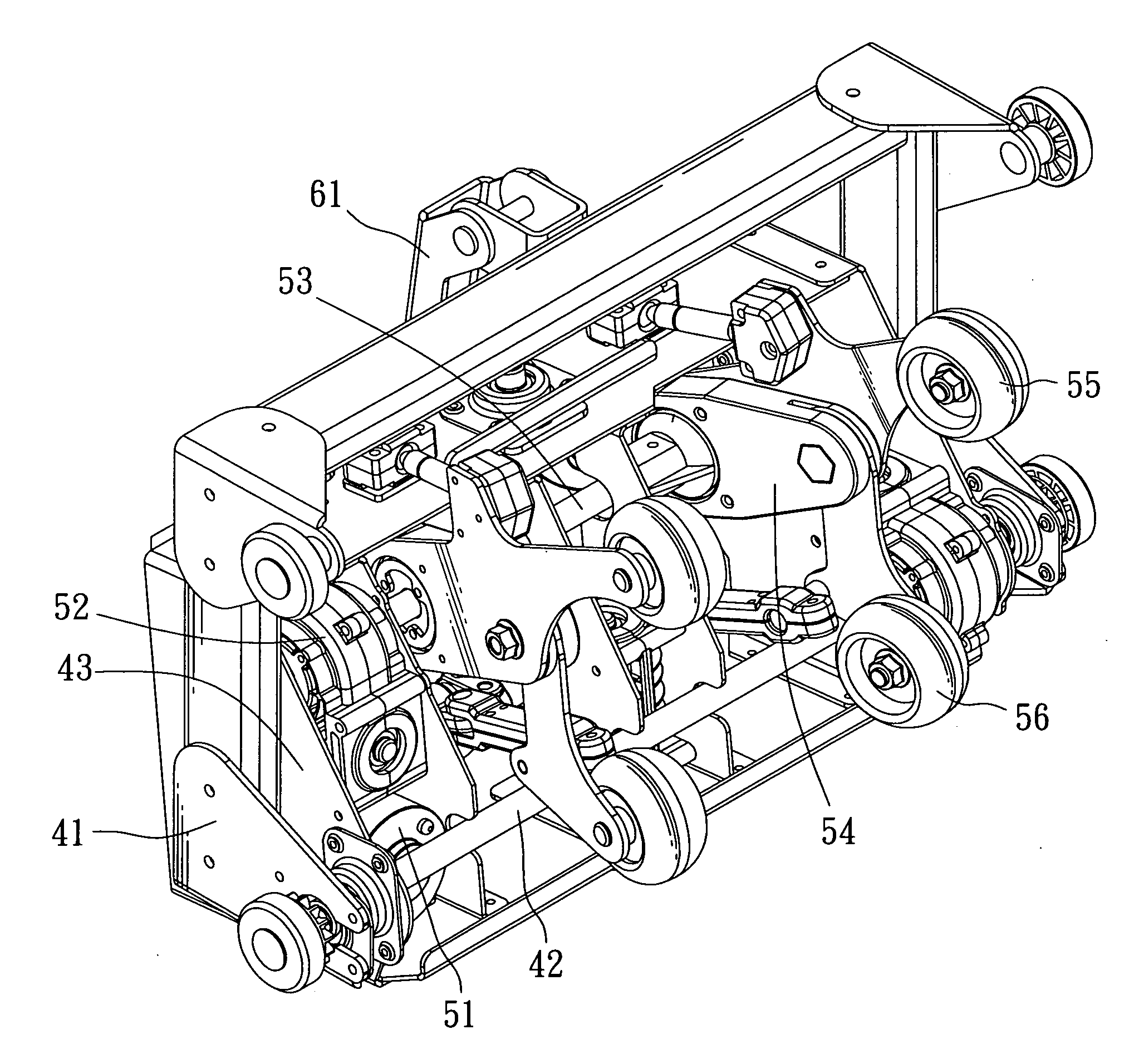
[0021]Referring to FIGS. 5-8, an angular adjusting mechanism for use in a massage device of a massage machine in accordance with the present invention comprises a frame 41 including a rotary shaft 42 axially disposed thereon and having a swing seat 43 axially mounted thereon, the swing seat 43 includes a rubbing mechanism having upper and lower massage rollers provided therein, and between the frame 41 and the swing seat 43 is defined with an angular adjusting mechanism, wherein the rubbing mechanism of the swing seat 43 includes a motor 51 for a driver, by which a transmitting assembly 52 is urged to transmit a rubbing shank 53, and at the two ends of the rubbing shank 53 are pivotally affixed two swing arms 54, individually, and each of the swing arms 54 includes upper and lower massage rollers 55 and 56 attached at the front end thereof. It is to be noted that the angular adjusting mechanism includes a frame 41 having a coupling member 61 axially fixed at the back thereof, and th...


PUM


Abstract

An angular adjusting mechanism for use in a massage device of a massage machine comprises a frame including a swing seat axially disposed thereon for pivotally rotating the angle and including upper and lower massage rollers provided thereon, and between the frame and the swing seat being defined with an angular adjusting mechanism, wherein the angular adjusting mechanism includes a bush axially fixed on the frame, the swing seat includes a driver attached thereon for urging the rotation of a screw, and another end of the screw screws with the bush; thereby during the rotation of the screw, the screw may vertically displace along the bush and actuate the swing seat to axially rotate along the frame for adjusting the swing angle and increasing the support strength of the upper and lower massage rollers.

Description

BACKGROUND OF THE INVENTION[0001]1. Field of the Invention[0002]The present invention relates to an angular adjusting mechanism for use in a massage device of a massage machine that during the rotation of a screw, the screw may vertically displace along a bush and actuate a swing seat to axially rotate along a frame for adjusting the swing angle and increasing the support strength of upper and lower massage rollers.[0003]2. Description of the Prior Arts[0004]Referring to FIGS. 1-3, TW Pat. No. 92211833 to Chen discloses “Massaging Device of Massaging Machine” including a rubbing mechanism and an angular adjusting mechanism, wherein a frame 11 includes front and rear rotary shafts 12, 13 disposed thereon, between which a holder 14 is couplingly disposed, wherein the front rotary shaft 12 includes a support 15 axially fixed thereon for affixing the rubber mechanism which contains a motor 21 for a driver secured on the rear end of the support 15, and the motor 21 urges a pulley set 22 ...

Claims


Application Information

Patent Timeline
IPC IPC(8): A61H15/00
CPCA61H15/0078A61H2015/0028A61H2201/0149A61H2201/1669A61H2205/081
Inventor CHEN, KO-PO
Owner CHEN KO PO
Why Eureka
Try Eureka