
Collar for increasing T-ratings and performance of firestop systems

a firestop and collar technology, applied in the field of fire prevention, can solve the problems of high t-rating, copper pipe failure, and non-insulated 6′′ diameter steel pipe failure, and achieve the effects of prolonging the time before the ignition of materials, prolonging the time, and saving resources

Inactive Publication Date: 2008-12-25
SPAIS GEORGE A
View PDF26 Cites 4 Cited by
  • Summary
  • Abstract
  • Description
  • Claims
  • Application Information

AI Technical Summary

Benefits of technology

"The present invention is a cooling system for a barrier used in a fireproof installation. The system uses a T-collar that surrounds a penetrant or conduit to prevent flames and hot gases from passing through. The collar includes a coolant package made of purified water or other suitable coolant. The collar is held in place by a hose clamp or other attachment means. The coolant package is designed to release the coolant when the temperature reaches a predetermined level, which is typically around 300F (149C. The technical effect of this invention is to extend the time that a firestop prevents the passage of flames and hot gases through a barrier, which can save lives and protect property during a fire outbreak."

Problems solved by technology

A non-insulated 6″ diameter steel pipe will fail the T-rating in an average of 15 to 30 minutes and copper pipes fail much more quickly.
The problem with low T-ratings is also compounded in thin concrete assemblies such as 2½ inch fluted decks.
There is not enough concrete in these thinner floor assemblies to thermally draw the heat away from the pipe.
Thinner floors make poor heat sinks.
There is a severe problem, however, with adding insulation to conduits.
During normal operation, conduits tend to heat up from resistance within energized wiring.
Insulating the conduits will not allow any excessive heat to escape and increases the chances of an electrical fire.

Method used


Image

  • Collar for increasing T-ratings and performance of firestop systems
  • Collar for increasing T-ratings and performance of firestop systems
  • Collar for increasing T-ratings and performance of firestop systems

Examples


Embodiment Construction

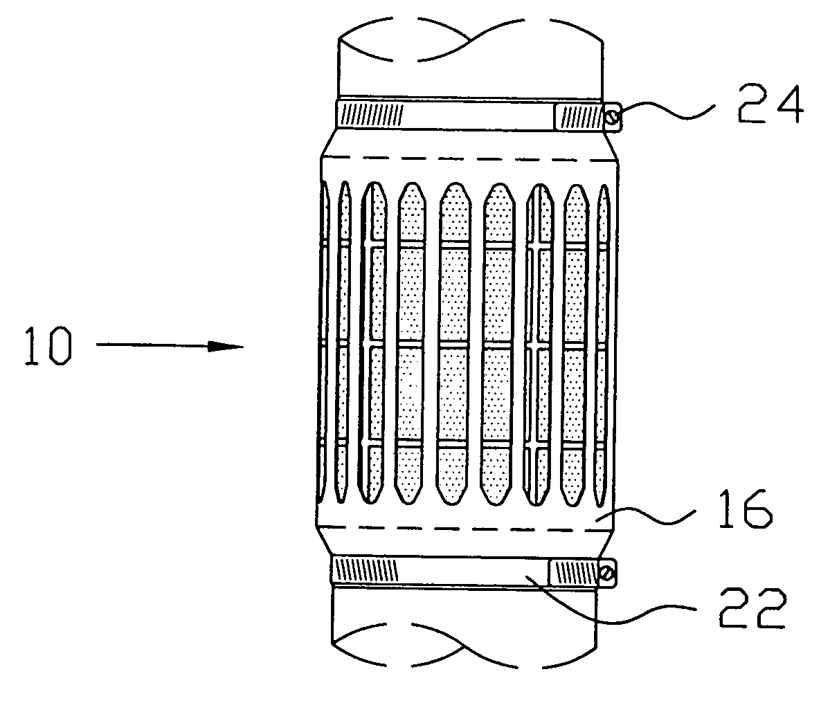
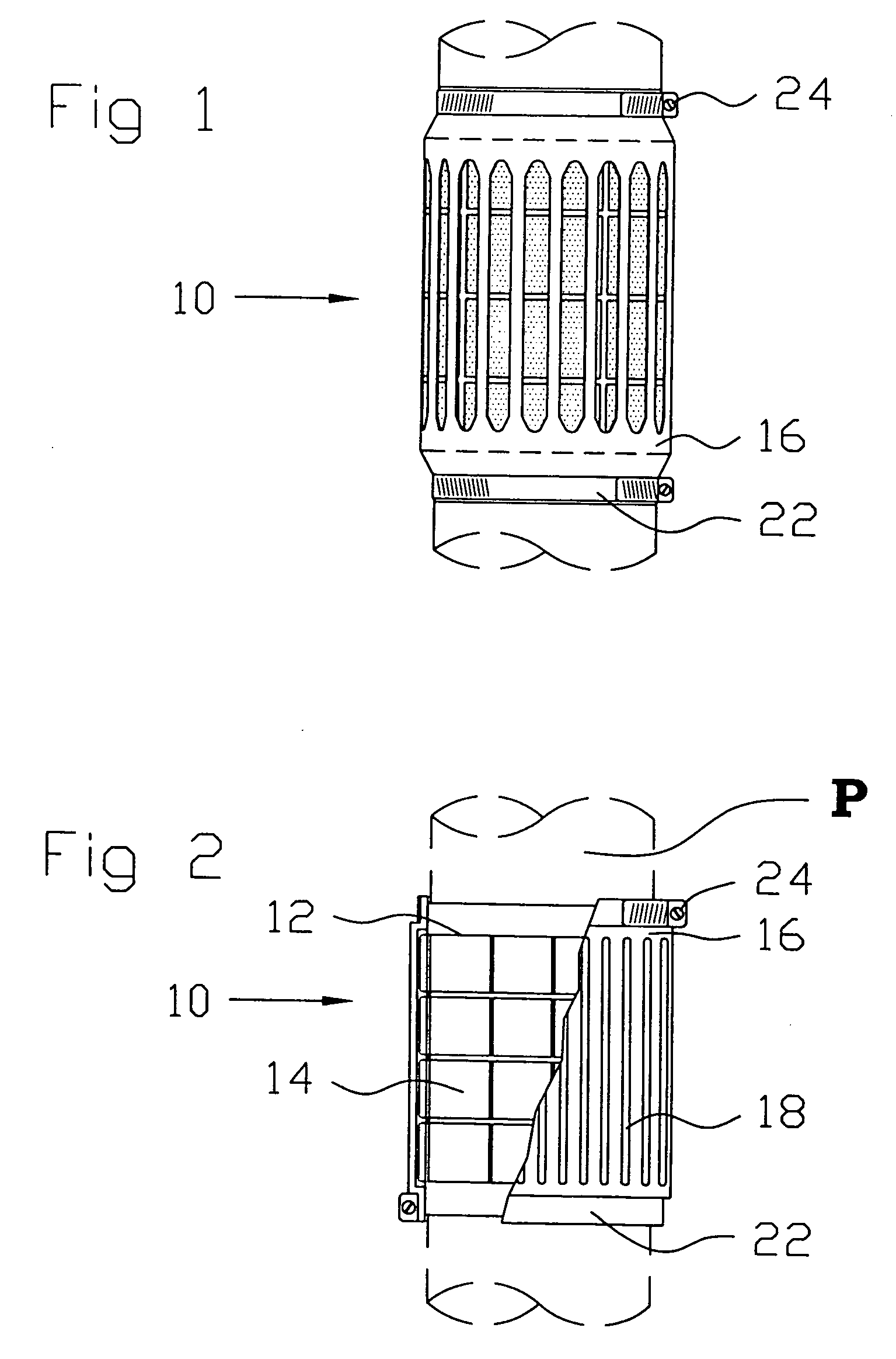
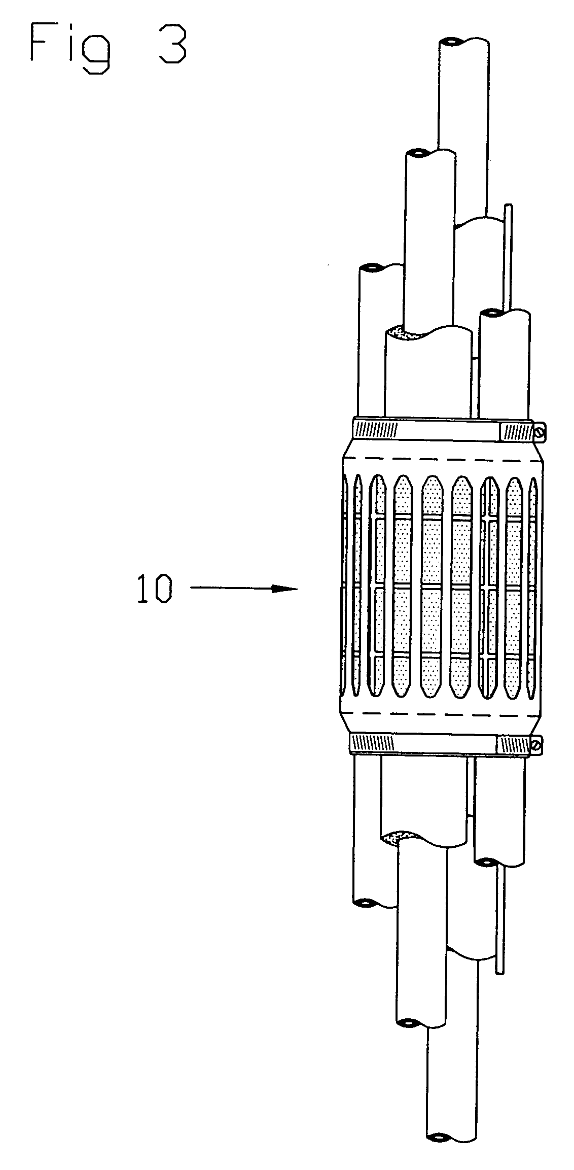
[0026]The present invention, known as a T-collar, is an assembly for preventing fire propagation by cooling penetrants from the non-fire side of a barrier and for extending the time that a firestop prevents the passage of flames and hot gases for a through penetration firestop installation. The T-collar provides a high level of cooling performance in an efficient design without complex installation procedures. The T-collar is not a firestop in and of itself, but rather improves the performance of a firestop.

[0027]Referring specifically to the drawings, the present invention T-collar 10 is depicted installed onto a variety of typical prior art penetrants, where in each case the prior art penetrant is labeled as reference letter P. In the figures, the penetrant P transverses a floor, wall or other barrier denoted as F. As is obvious and depending on the application, the penetrant can be a pipe, cable bundle or other such conduit, or a plurality of pipes, cable bundles or conduits, and...


PUM


Abstract

An assembly for cooling a penetrant from the non-fire side of a barrier and to extend the time that a firestop prevents the passage of flames and hot gases of a through penetration firestop installation. The present invention includes an encapsulation wrap that is positioned adjacent to and surrounding a penetrant or conduit. The encapsulation wrap comprises a plurality of individual coolant packages, each of which contains purified water or other appropriate coolant. An exterior banding structure is provided which is positioned adjacent to the encapsulation wrap and includes a plurality of vents to improve its heat dissipation properties and may include exterior fins. The encapsulation wrap and exterior banding are positioned and held in place by a hose clamp or other suitable attachment means. The packets of coolant are engineered to release a controlled amount of coolant when the coolant and / or penetrant achieves a predetermined temperature.

Description

CROSS REFERENCE TO RELATED APPLICATION[0001]This application is a Continuation of previously filed application bearing Ser. No. 10 / 966,926.FIELD OF THE INVENTION[0002]The present invention relates to the field of fire prevention, or more specifically firestopping, and improves a firestop's performance by means of cooling penetrating members. More specifically the present invention includes a coolant encapsulation wrap that surrounds a conduit or penetrant and further includes exterior banding which provides for heat dissipation through the use of fins, vents or other described means.BACKGROUND OF THE INVENTION[0003]Firestop systems for pipes and conduits are typically tested to ASTM E 814, Test Method for Fire Tests of Through-penetration Firstops, although other standards exist. This method produces two different ratings: one called the F-rating and the other called the T-rating.[0004]The F-rating is a measure of the minimum amount of time that a design has shown to prevent the pro...

Claims


Application Information

Patent Timeline
Patent Type & Authority Applications(United States)
IPC IPC(8): E04B1/94
CPCF16L5/04Y10S52/05
Inventor SPAIS, GEORGE
Owner SPAIS GEORGE A
Learn More