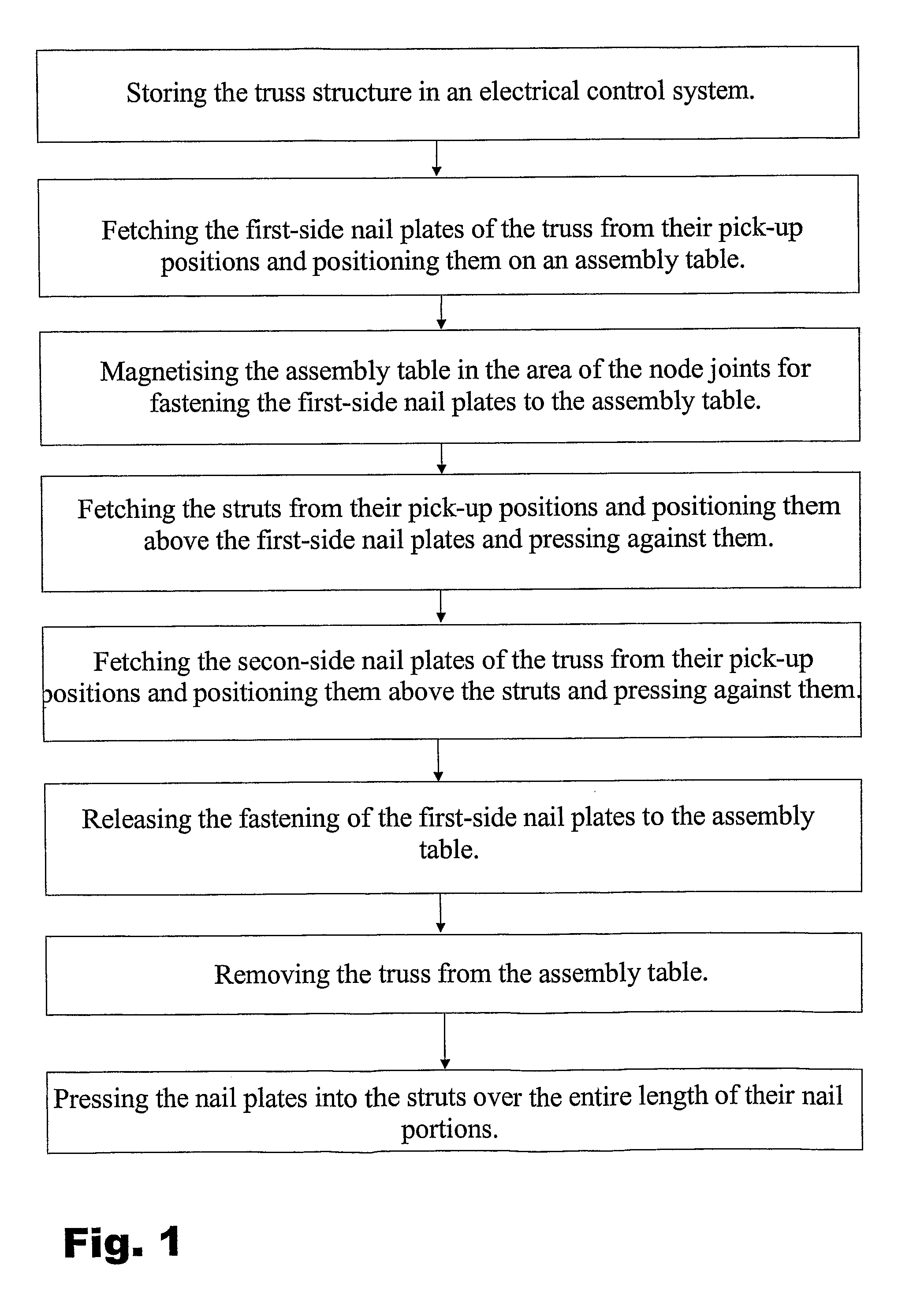
[0009]The invention is especially intended to disclose a novel automatic method and apparatus for manufacturing a nail plate truss without a setting, by means of which method and apparatus trusses having different shape and size can be manufactured effectively and with high accuracy, and which apparatus, compared to prior art apparatuses, is simpler and requires less maintenance.SUMMARY OF THE INVENTION
[0018]Performing the steps described above as controlled by the
electric control system means that said steps are performed automatically by means especially provided for each step. For transferring and positioning of parts, for example, handling members can be used operated by precisely positioned electric high-speed linear motors provided with slides for linear motors moving in a magnetic trail, to which the handling members have been fastened. By
automation, the manufacture is accelerated, and positioning the parts becomes more precise while simultaneously reducing the possibility of errors compared to manual assembly. Said pick-up positions may be storages or intermediate positions for parts outside the assembly table or in the area of the table, to which parts needed at each time are brought one by one. In their respective pick-up positions, both the struts and the nail plates are preferably in precisely defined locations in order to be gripped at given locations, when picking up by automatic handling means. At this, the location of the parts is under control during the entire transfer. If the pick-up position is a storage containing several different parts, the parts are preferably provided with identifications, e.g. bar codes or the like allowing the handling members to identify, for example, the strut needed in each case.
[0025]According to the invention, the apparatus for manufacturing the nail plate truss without setting includes an electric
control system in which the structure of the truss, and the positions of its parts can be stored. The
control system may include, for example, both a computer and
software installed therein, and data transfer connections between the computer and the apparatuses controlled by it. The
control system allows the nail plate trusses to be manufactured automatically, without manual working steps, thus contributing to the effectiveness of the manufacture, and decreasing the production costs. The accuracy also is improved as human errors, for example, in measuring the positions, are eliminated. Such a control system also can be integrated as a part of the remaining
production control system of the factory, allowing the apparatus to be operated centrally as a part of the controlled
production line.
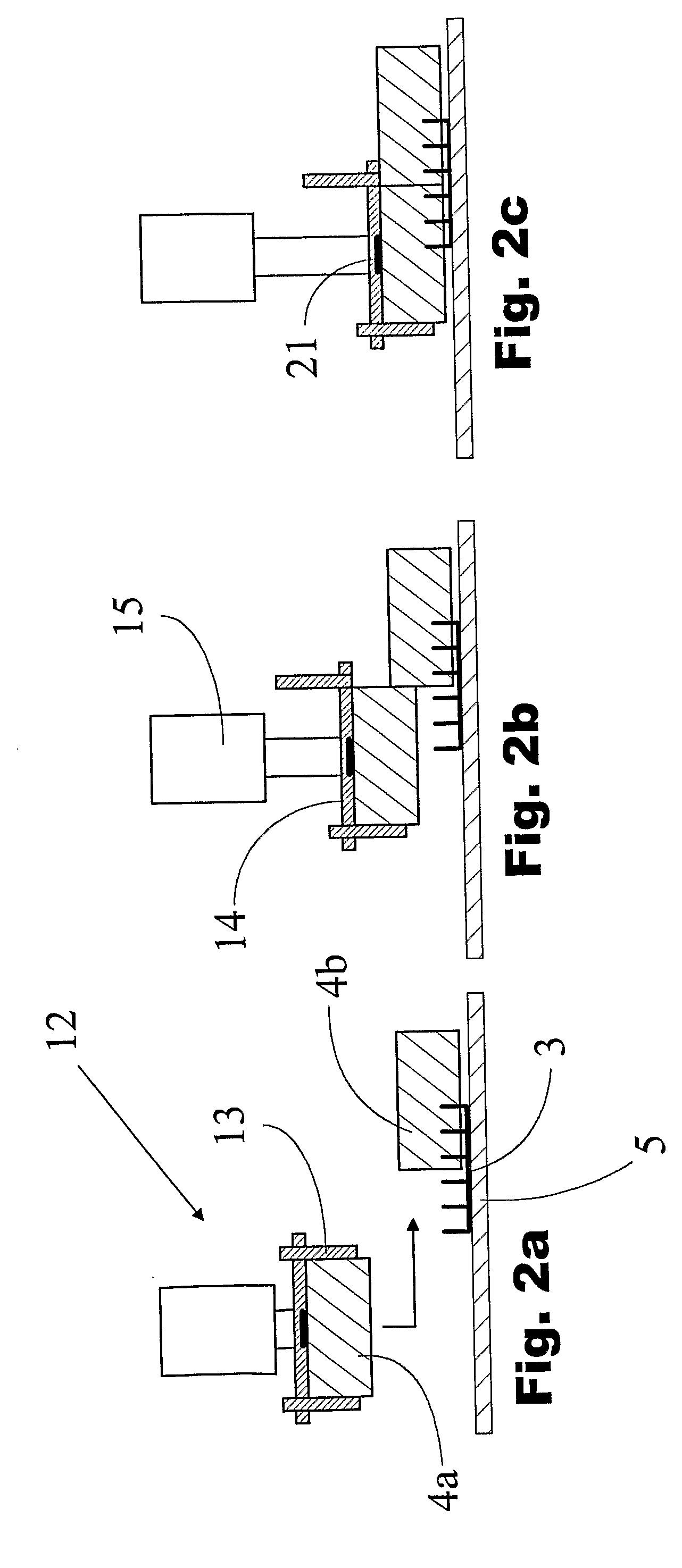
[0033]The handling means also may comprise vibrating means for vibrating the
support surface, so as to increase the effectiveness while pressing the nail plate and the strut against each other.
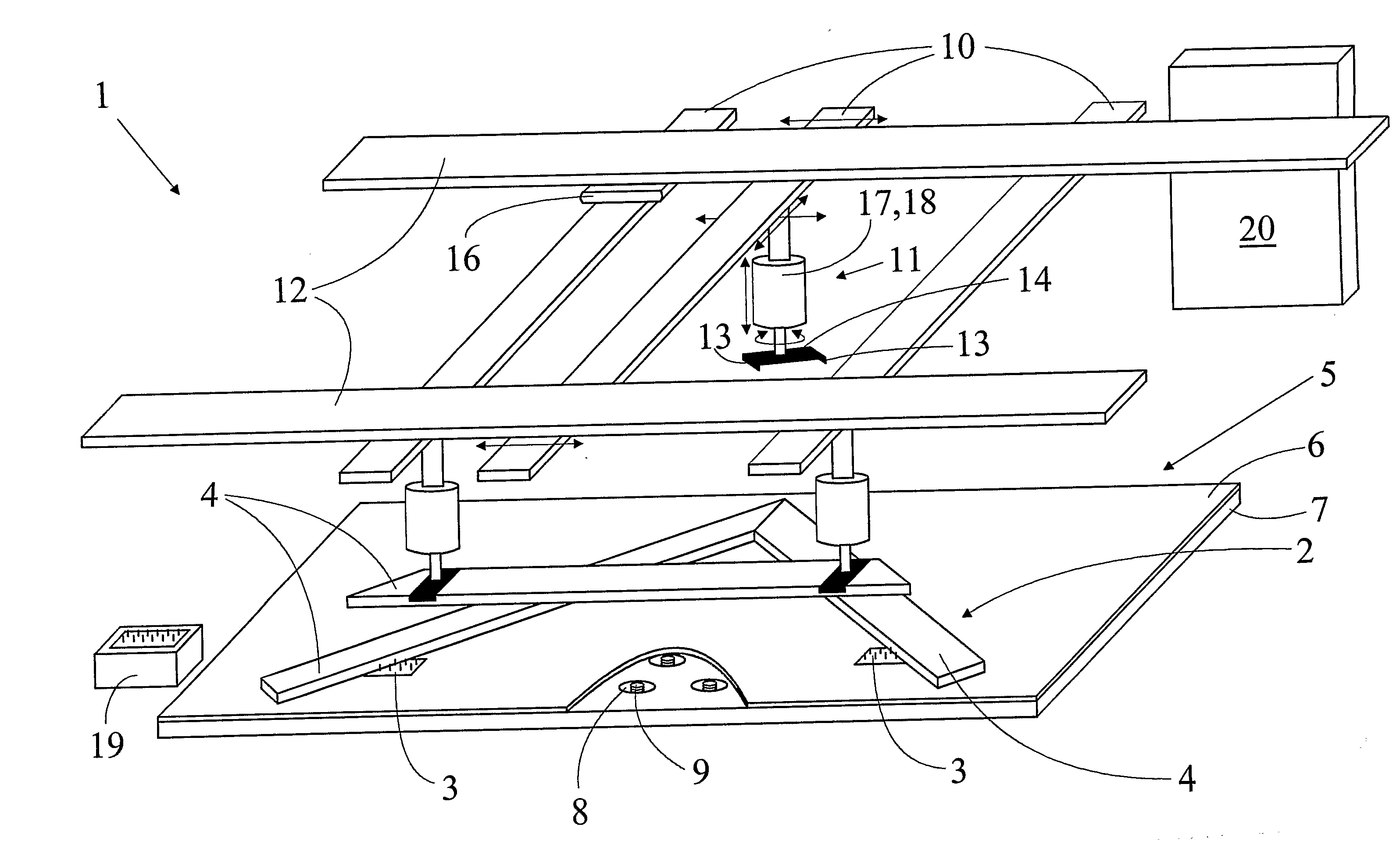
[0034]In a preferred embodiment of the invention, the transfer means first include linear guides arranged above the assembly table, substantially parallel thereto, carrying the handling members for transferring the handling members along the first linear guides. Furthermore, the transfer means comprise second linear guides supported above the assembly table, for example, to the frame of the apparatus, carrying the first linear guides, and arranged perpendicularly thereto, likewise disposed substantially parallel to the assembly table for transferring the first linear guides therealong. Hence, by means of linear movements in two directions, the handling member can be brought to every given position above the assembly table. The linear guides extend preferably over the entire handling line and so far therebeyond that fetching parts from pick-up positions outside the assembly table, and transfer of the truss away from the assembly table is enabled. Preferably, the handling member also is arranged to be horizontally movable, transversely in relation to the first linear guide carrying it. This allows moving and assembling of the struts also parallel to the first linear guide, by holding the strut with the handling members of the first linear guides. For accomplishing the movements along the linear guides, the transfer means also comprise drive means, for example linear electric motors or other drive means capable of achieving sufficient speed and positioning precision.
[0036]Utilising the inventive method and apparatus for the manufacture of nail plate trusses, different advantages are achieved, as is described above, compared to previously used methods. Firstly, the assembly of nail plate trusses in which conventionally a lot of human work was involved, can be completely automated resulting in an acceleration of the manufacture. Additionally, time is spared remarkably by the essential feature of the invention that a separate change of setting between the different truss types is not needed, since positioning of the parts is directly based on position information stored in the electric control system, and on positioning of the handling members as controlled by the control system. By
automation, the precision also will be improved and the possibility of errors minimised. The
automation system can be incorporated as a part of the remaining control system so as to be operated by the
production control system of the entire production
plant. According to the invention, the nail plate truss is manufactured without turning upside down known from prior art, for fastening the second-side nail plates. This eliminates the risk for truss to be distorted during turning. Neither are complicated and failure-prone to turning means needed known from prior art apparatuses. Unlike the stops according to prior art, movable in the assembly table, the apparatus is not sensitive to problems caused by wooden material loosening from the trusses, and other impurities, as the assembly table may be very simple, for example, merely a level of steel.

