Discharge Device and Air Purification Device

a discharge device and air purification technology, applied in the direction of corona discharge, heating types, separation processes, etc., can solve the problems of streamer discharge state, streamer discharge is not produced stably, acutely susceptible to being easily influenced by various affectors, etc., to reduce the discharge delay time caused at the time of streamer discharge, and generate streamer discharge stably

Inactive Publication Date: 2008-12-25
DAIKIN IND LTD
View PDF25 Cites 7 Cited by
  • Summary
  • Abstract
  • Description
  • Claims
  • Application Information

AI Technical Summary

Benefits of technology

[0028]In accordance with the first invention, it is arranged such that a voltage whose voltage frequency (fv) is equal to or higher than the discharge frequency (fs) is applied to both the electrodes (41, 42). In addition, in each of the electrodes (41, 42), the discharge delay time caused at the time of streamer discharge is reduced. Consequently, the discharge loss is suppressed in both the electrodes (41, 42), thereby making it possible to stably generate streamer discharges.
[0029]In accordance with the second invention, it is arranged such that the voltage frequency (fv) is determined based on the discharge frequency (fs) estimated from the gap length (G). This arrangement ensures that the voltage frequency (fv) is made equal to or higher than the discharge frequency (fs), thereby making it possible to reduce the discharge delay time at the time of streamer discharge. This therefore ensures that the discharge losses of the discharge device are suppressed without failing.
[0030]In accordance with the third invention, it is arranged such that a voltage, whose voltage frequency (fv) is not less than the discharge frequency (fs) and not less than 20[kHz], is applied. Consequently, the voltage frequency (fv) is made equal to or higher than the discharge frequency of a general streamer discharge (less than about 20 [kHz]), thereby making it possible to reduce the discharge delay time at the time of streamer discharge.
[0031]In addition, if the frequency of a voltage, (fv), is made equal to or higher than 20[kHz], this allows the frequency of sound associated with the outputting of the voltage to become higher than the range of human hearing, thereby making it possible to suppress noises generated in the vicinity of the electric power supply means (45).
[0032]In accordance with the fourth invention, it is arranged such that the amplitude (Vp-p) of the cyclically varying voltage is made equal to or lower than 10% of the average voltage (Va). This arrangement narrows the range of variation of the voltage that is applied to both the electrodes (41, 42), thereby making it possible to prevent the voltage that is applied to both the electrodes (41, 42) from reaching a spark region. As a result, the generation of a spark is inhibited and the streamer discharge stability of the discharge device is improved.
[0033]In accordance with the fifth invention, by incorporating a discharge device according to any one of the first to fourth inventions into an air purification device, it becomes possible to reduce the discharge delay time at the time of streamer discharge in the air purification device. This reduces the discharge losses of the air purification device, thereby making it possible to stably generate streamer discharges. Accordingly, the air purification efficiency of the air purification device can be improved.

Problems solved by technology

Such a streamer discharge type discharge device provides high decomposition efficiency for odorous components and harmful components, but on the other hand it has the property that the streamer discharge state (e.g. the frequency of occurrence of streamer discharges and the streamer discharge generation status) is acutely susceptible to being easily influenced by various affectors.
If, in consequence of either dimensional or assembly errors made during fabrication of discharge electrodes, or dust adhesion between electrodes, the electrodes vary from each other in discharge characteristic, this arises a problem that streamer discharges are not produced stably.
If, in this way, no streamer discharge is produced in a certain electrode, this reduces the amount of generation of activated species (fast electron, radical et cetera), thereby producing the problem that the air purification device equipped with a discharge device of the type described above is reduced in air purification efficiency.

Method used


Image

  • Discharge Device and Air Purification Device
  • Discharge Device and Air Purification Device
  • Discharge Device and Air Purification Device

Examples


Embodiment Construction

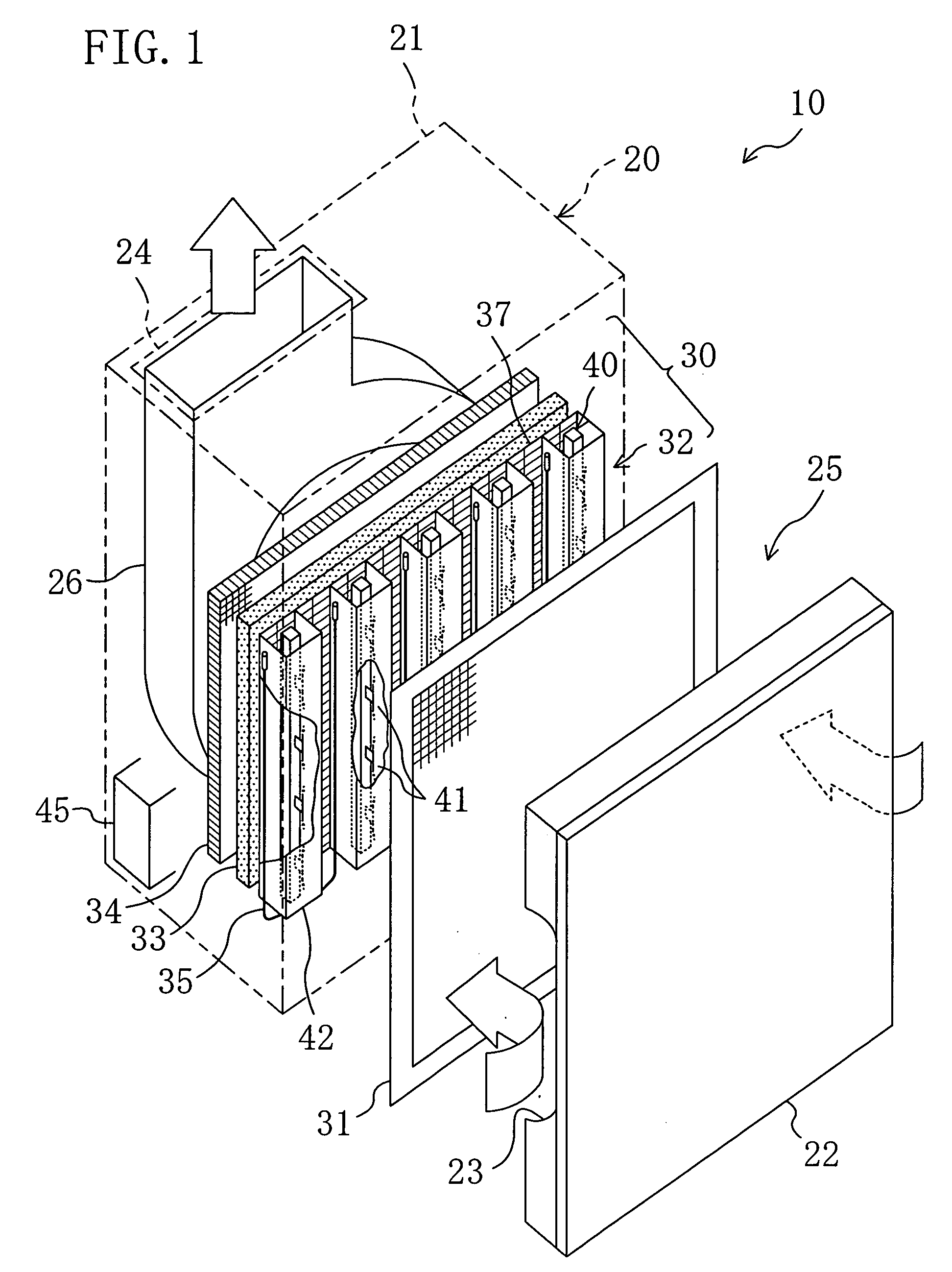
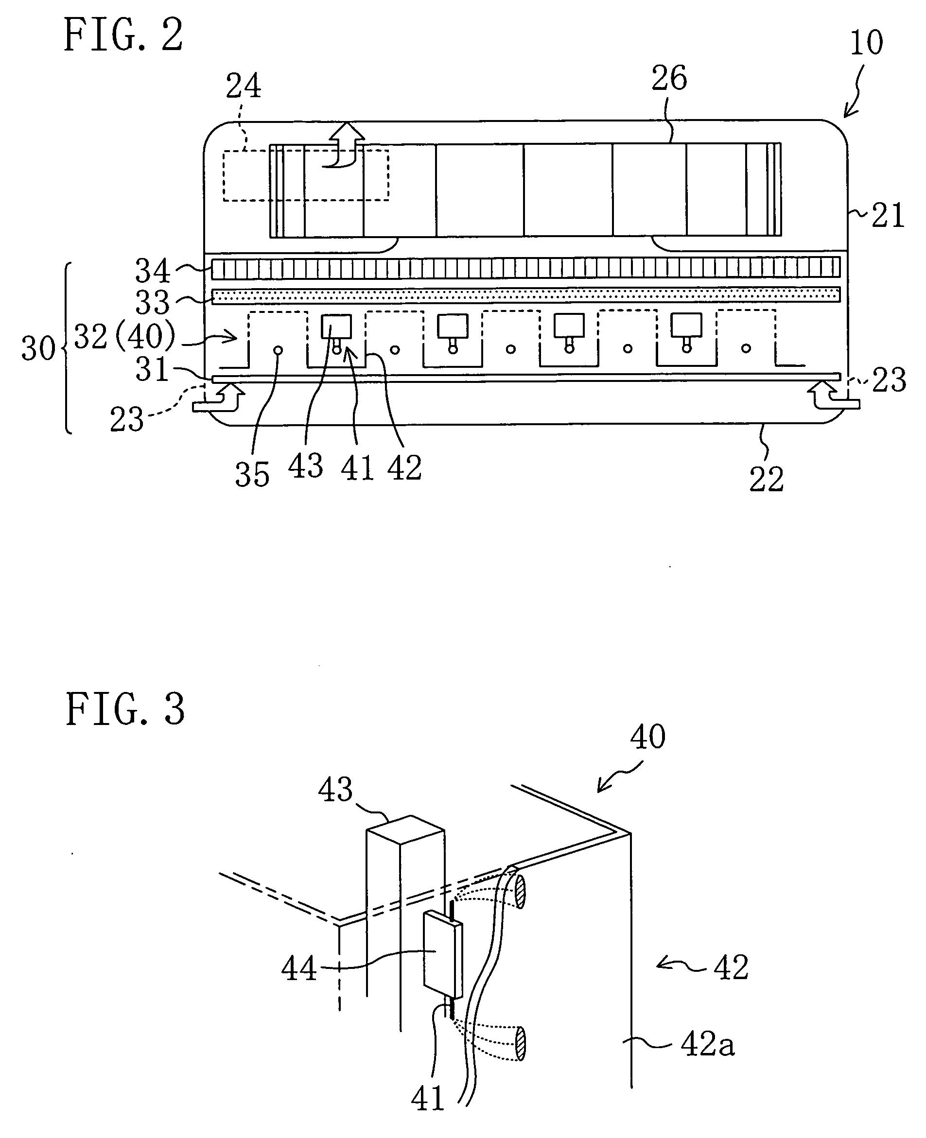
[0054]An embodiment of the present invention is described with reference to FIGS. 1-4.

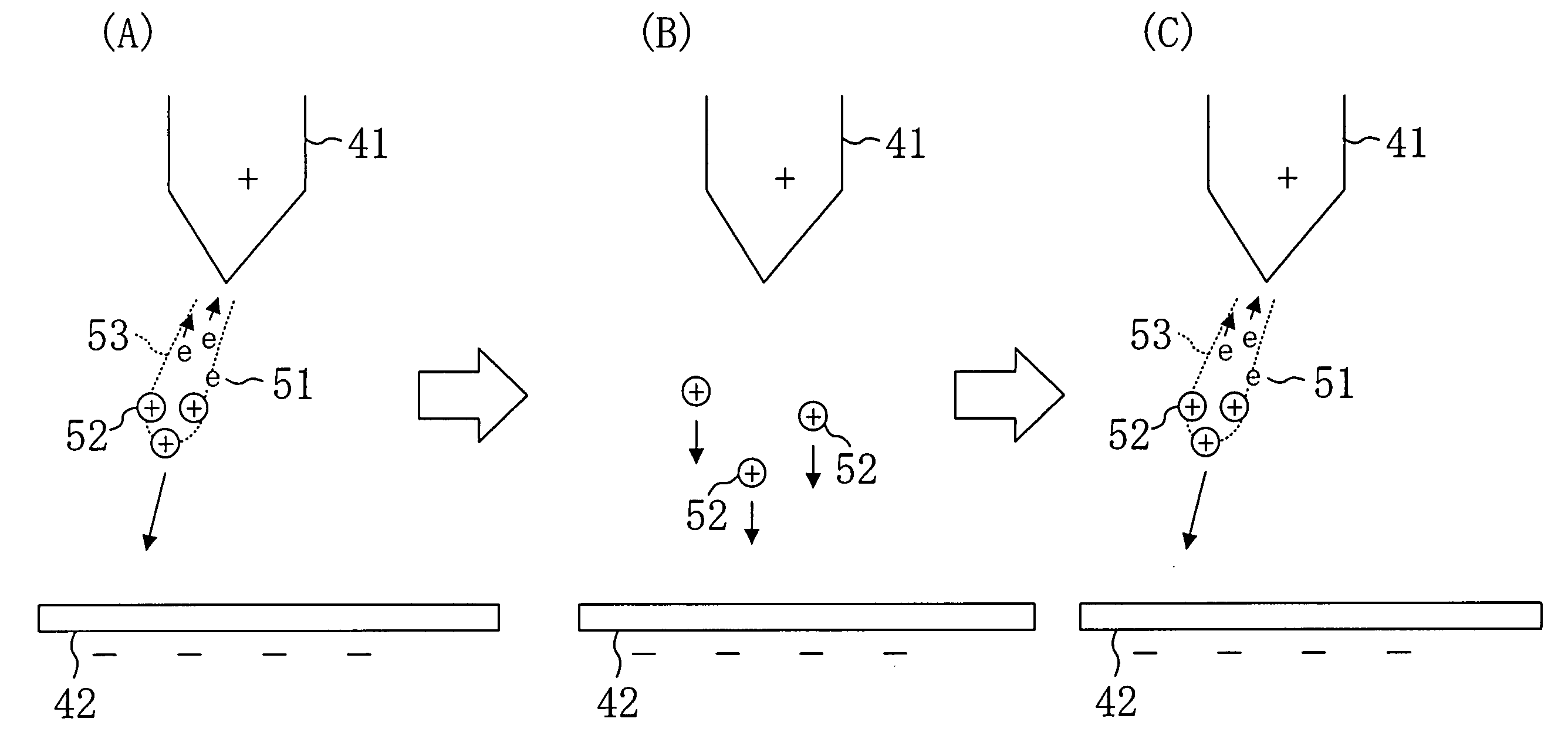
[0055]FIG. 1 is a perspective view which illustrates in exploded manner an air purification device (10) according to the present embodiment and FIG. 2 is a diagram which shows the inside of the air purification device (10) when viewed from above. This air purification device (10) is a consumer air purification device intended for use in general household and small stores. In addition, the air purification device (10) is an air purification device of the so-called streamer discharge type adapted to generate a low temperature plasma by streamer discharge and purify air to be treated with the aid of the low temperature plasma.

[0056]The air purification device (10) includes a casing (20). The casing (20) is made up of a box-like casing main body (21) with an open end surface and a front plate (22) which is placed on the open end surface. An air suction opening (23) is formed in each side surface of the...


PUM

PropertyMeasurementUnit
voltageaaaaaaaaaa
frequencyaaaaaaaaaa
distanceaaaaaaaaaa

Abstract

The frequency of a cyclically varying voltage, (fv), is made equal to or higher than the frequency of a streamer discharge, (fs), thereby making it possible to reduce the discharge delay time which is caused in a single streamer discharge.

Description

TECHNICAL FIELD[0001]The present invention relates to a discharge device which causes a streamer discharge to be initiated upon application of a cyclically varying voltage, and to an air purification device which is equipped with such a discharge device.TECHNICAL FIELD[0002]Air purification devices which are equipped with discharge devices are conventionally utilized as means for decomposing and removing, by the use of a plasma generated by electric discharge, odorous components, harmful components, and other substances. Among these various air purification devices, an air purification device of the streamer discharge type in which a low temperature plasma is generated by streamer discharge is a preferable technique for decomposing and deodorizing harmful components because of its high air purification efficiency with relatively less electric power consumption.[0003]The above streamer discharge type air purification device includes, as a discharge device, a plurality of discharge el...

Claims


Application Information

Patent Timeline
Patent Type & Authority Applications(United States)
IPC IPC(8): B03C3/41H05H1/24A61L9/18B01D53/32B01J19/08F24F3/16H01T19/00
CPCB01D53/32F24F3/166H01T19/00F24F8/192Y10S323/903Y02A50/20
Inventor TANAKA, TOSHIOKAGAWA, KENKICHIMOTEGI, KANJI
Owner DAIKIN IND LTD
Why Eureka
Try Eureka